8.
Electrical Hazard: Only qualified personnel should perform installation procedures. Riesgo Electrico: Solamente personal calificado debe realizar procedimientos de instalacion. Elektrischer Gefahrenhinweis: Installationen sollten nur durch ausgebildetes und qualifiziertes Personal vorgenommen werden. Notice Enterasys Networks reserves the right to make changes in specifications and other information contained in this document and its web site without prior notice.
Regulatory Compliance Information Federal Communications Commission (FCC) Notice This device complies with Part 15 of the FCC rules. Operation is subject to the following two conditions: (1) this device may not cause harmful interference, and (2) this device must accept any interference received, including interference that may cause undesired operation. NOTE: This equipment has been tested and found to comply with the limits for a class A digital device, pursuant to Part 15 of the FCC rules.
Electromagnetic Compatibility (EMC) This product complies with the following: 47 CFR Parts 2 and 15, CSA C108.8, 2004/108/EC, EN 55022, EN 61000‐3‐2, EN 61000‐3‐3, EN 55024, AS/NZS CISPR 22, VCCI V‐3. Compatibilidad Electromágnetica (EMC) Este producto de Enterasys cumple con lo siguiente: 47 CFR Partes 2 y 15, CSA C108.8, 2004/108/EC, EN 55022, EN 55024, EN 61000‐3‐2, EN 61000‐3‐3, AS/NZS CISPR 22, VCCI V‐3.
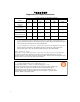
ѻક䇈ᯢк䰘ӊ Supplement to Product Instructions 䚼ӊৡ⿄ (Parts) 䞥ሲ䚼ӊ (Metal Parts) ⬉䏃ഫ (Circuit Modules) ⬉㓚ঞ⬉㓚㒘ӊ (Cables & Cable Assemblies) ล᭭㘮ড়⠽䚼ӊ (Plastic and Polymeric parts) ⬉䏃ᓔ݇ (Circuit Breakers) ƻ˖ 䪙 3E ᳝↦᳝ᆇ⠽䋼ܗ㋴ (Hazardous Substance) ⒈㘨㣃 ∲ 䬝 ݁Ӌ䫀 3%% +J &G &U ⒈Ѡ㣃䝮 3%'( h ƻ ƻ ƻ ƻ ƻ h ƻ ƻ ƻ ƻ ƻ h ƻ ƻ ƻ ƻ ƻ ƻ ƻ ƻ ƻ ƻ ƻ ƻ ƻ ƻ ƻ ƻ ƻ 㸼⼎䆹᳝↦᳝ᆇ⠽䋼䆹䚼ӊ᠔᳝ഛ䋼ᴤ᭭Ёⱘ䞣ഛ SJ/T 11363-2006 ᷛޚ㾘ᅮⱘ䰤䞣㽕∖ҹϟDŽ Indicates that the concentration of the hazardou
VCCI Notice This is a class A product based on the standard of the Voluntary Control Council for Interference by Information Technology Equipment (VCCI). If this equipment is used in a domestic environment, radio disturbance may arise. When such trouble occurs, the user may be required to take corrective actions. BSMI EMC Statement — Taiwan This is a class A product. In a domestic environment this product may cause radio interference in which case the user may be required to take adequate measures.
Declaration of Conformity Application of Council Directive(s): Manufacturer’s Name: Manufacturer’s Address: European Representative Address: Conformance to Directive(s)/Product Standards: Equipment Type/Environment: 2004/108/EC 2006/95/EC Enterasys Networks, Inc. 50 Minuteman Road Andover, MA 01810 USA Enterasys Networks, Ltd.
2. RESTRICTIONS. Except as otherwise authorized in writing by Enterasys, You may not, nor may You permit any third party to: (a) Reverse engineer, decompile, disassemble or modify the Program, in whole or in part, including for reasons of error correction or interoperability, except to the extent expressly permitted by applicable law and to the extent the parties shall not be permitted by that applicable law, such rights are expressly excluded.
8. AUDIT RIGHTS. You hereby acknowledge that the intellectual property rights associated with the Program are of critical value to Enterasys, and, accordingly, You hereby agree to maintain complete books, records and accounts showing (i) license fees due and paid, and (ii) the use, copying and deployment of the Program.
Contents About This Guide Who Should Use This Guide ........................................................................................................................... xiii How to Use This Guide .................................................................................................................................... xiii Related Documents .........................................................................................................................................
IOM Status LEDs ..................................................................................................................................... 3-3 Fixed and IOM Port LEDs ........................................................................................................................ 3-3 Using the Reset Button ................................................................................................................................... 3-4 Removing the Switch from a Rack ..................
A-8 A-9 A-10 A-11 A-12 A-13 A-14 A-15 A-16 A-17 A-18 A-19 A-20 A-21 A-22 A-23 A-24 MGBIC-LC01/MGBIC-MT01 Operating Range ..................................................................................A-6 MGBIC-02 Specifications ...................................................................................................................A-6 MGBIC-LC03 Optical Specifications...................................................................................................
xii
About This Guide This guide provides an overview, specifications and instructions for installing the Enterasys® G‐Series Ethernet Switch in a standard 19‐inch equipment rack, or on a suitable flat surface. This guide also explains how to interpret the system status LEDs to facilitate troubleshooting when necessary, and also provides information on how to contact Enterasys Networks for additional help.
Document Conventions Document Conventions The following typographical conventions and icons are used in this guide. blue type Indicates a hypertext link. When reading this document online, click the text in blue to go to the referenced figure, table, or section. Lowercase x Indicates the general use of an alphanumeric character (for example, 6x1xx, the x’s indicate a combination of numbers or letters). Note: Calls the reader’s attention to any item of information that may be of special importance.
Getting Help Getting Help For additional support related to the G‐Series switch, the IOMs, or this document, contact Enterasys Networks using one of the following methods: World Wide Web www.enterasys.com/support/ Phone 1-800-872-8440 (toll-free in U.S. and Canada) or 1-978-684-1000 To find the Enterasys Networks Support toll-free number in your country: www.enterasys.com/support Internet mail support@enterasys.com To expedite your message, please type [Switching] in the subject line.
Getting Help xvi About This Guide
1 Introduction The G‐Series Ethernet switch is a modular, high‐density switch designed to handle networking demands in commercial and institutional settings, including education, government, and financial environments. Overview The G‐Series product family includes the G3G124‐24, G3G124‐24P and G3G170‐24 base systems.
Features Figure 1-2 1 2 3 4 G3G124-24 Switch (rear view) with 1200 and 400-watt power supplies installed AC power inlet PWR Slot 2 with 1200-watt power supply PWR Slot 1 with 400-watt power supply Captive screw 5 6 7 Memory slot with coverplate (reserved for future use) Password reset button Optional module slot (reserved for later use) Features The G‐Series switches include the following features: • • A base system (chassis) containing fixed interfaces in the lower left front panel – 24 RJ45 (10/
Features • Standalone or Rack Mountable Chassis The G‐Series Ethernet switch can be installed as a freestanding unit on a shelf or table. Optionally, it can be mounted into a standard 48.26‐centimeter (19‐inch) equipment rack. • Optional PoE – PoE is installed on the G3G124‐24P base system. – G3G‐POE, a 24‐port PoE module is available for any installed G3G‐24TX IOM or the G3G124‐24 base system. Refer to “PoE (Power over Ethernet) Support” on page 1‐3 for more information.
Features common mode voltage on the signal pair. PoE exploits this fact by using two twisted pairs as the two conductors to supply a direct current. One pair carries the power supply current and the other pair provides a path for the return current. While several proprietary legacy implementations of PoE have been deployed by LAN equipment vendors, in 2003 the IEEE published the IEEE 802.3af specification, which is part of the 802.3 suite of standards. The switch is fully compliant with the IEEE 802.
2 Installation This chapter provides the instructions to install the G3G124‐24, G3G124‐24P and G3G170‐24. Unless otherwise noted, the instructions apply to all switches. Equipment needed: • Phillips screwdriver • Flat blade screwdriver Electrical Hazard: Only qualified personnel should install or service this unit. Riesgo Eléctrico: Nada mas personal capacitado debe de instalar o darle servicio a esta unida.
Unpacking the G-Series Switch Unpacking the G-Series Switch Note: Unpack the G-Series Ethernet switch components only as needed. Leave the components in their respective shipping cartons until you are ready to install that component. Save all shipping materials in the event that the chassis has to be repacked. Shipped With the Switch Inspect the contents for any signs of physical damage. Contact Enterasys Networks if it is damaged. Refer to “Getting Help” on page xv for details.
Order of Installation Steps Order of Installation Steps Once a suitable site has been chosen, proceed to install the G‐Series Ethernet switch components. It is recommended that the installation proceed in this order: 1. (Optional) Install a PoE card. Refer to “G3G124‐24 Optional PoE Module Installation Considerations” on page 2‐3. 2. Mount the chassis to a 19‐inch (48.26‐centimeter) rack or other secure location. Refer to “Mounting the Switch” on page 2‐3. 3. Install power supply module(s).
Mounting the Switch Placing the Switch on a Flat Surface When installing the switch on a flat surface, the installation of the rubber feet is recommended to prevent the switch from sliding. Also, the surface must be able to support 15.5 kg (35 lbs) of static weight. To install the rubber feet, proceed as follows: 1. Place the switch upside down on a sturdy flat surface. 2. Remove the four rubber feet from the shipping box. 3.
Installing and Removing a Power Supply Figure 2-1 Attaching the Brackets to the Switch (G3G124-24 with G3G-24TX IOM shown) 1 Screws 4. 2 Rack-mount brackets Using your mounting hardware, attach the front of the brackets to the rack. Tighten securely. Installing and Removing a Power Supply The following power supplies are available to be purchased from Enterasys for installation on the G‐Series switch.
Installing and Removing a Power Supply Power Supply Planning As shown in Table 2‐1, when two power supplies are installed and power redundancy (the default switch setting) has not been disabled through the CLI, the power supplies share the load equally and provide power redundancy. If one power supply fails or is removed (hot swapped) for any reason, the other power supply takes up the load.
Installing and Removing a Power Supply Power Supply Addition or IOM Removal When a power supply is added or an IOM module is removed, the G3 responds to the increase in available power by: 1. Detecting the power supply addition and recalculating available power (adding capacity of the new power supply or accounting for less load with removal of an IOM module). 2. Subtracting the power capacity for its base system and all installed modules from available power. 3.
Installing and Removing a Power Supply Figure 2-2 Installing a Power Supply Module (1200-watt module into PWR 2 slot shown) 1 Power supply 2 Power supply handle 3 Captive screws 7. Secure the power supply to the chassis by tightening the captive screws. 8. If you are installing an additional power supply, repeat step 4 through step 7. If not, ensure that the unused power slot has a coverplate installed over it.
Installing and Removing an IOM Installing and Removing an IOM Caution: There are hazardous moving parts inside the base unit. Keep fingers and other body parts away from spinning fans when installing or removing IO modules. Precaución: El interior de la unidad que sirve de base contiene partes móviles peligrosas. Mantenga los dedos y cualquier otra parte del cuerpo lejos de las aspas de los ventiladores cuando realice la instalación o al retirar los módulos IO.
Installing and Removing an IOM Figure 2-3 Installing a PoE module in the G3G-24TX IOM 1 2 3 Fastening screws PoE daughter card module IOM to PoE connector 4 5 IOM connector G3G-24TX IOM module (motherboard) 4. Using the screws shipped with the PoE module, firmly attach the PoE module to the IOM. Installing an IOM If you have one or more IOMs that you wish to install into the switch, you should do so before you connect power to the switch.
Installing and Removing an IOM Figure 2-4 Installing an IOM (G3G-24TX with optional PoE shown) 1 2 3 IOM slot 2 IOM handle Captive screw 4 5 Optional PoE module IOM module 7. To install additional modules, remove the coverplates from the slots and repeat earlier steps. Save coverplates for optional future use. 8. After completing all module installation, be sure to install coverplate(s) over any unused IOM slot(s) to contain EMI radiation and ensure proper air circulation.
Connecting Power to the Switch Caution: Use caution when removing an IOM on which you have optional PoE installed to avoid damaging the PoE module. Precaución: Tenga cuidado al retirar un IOM que tenga un módulo PoE instalado, ya que éste puede dañarse. 4. Replace the slot’s coverplate. Connecting Power to the Switch You can install a single primary source of power or provide two sources of power for redundancy, as described in the following sections.
Connecting to the Console Port Refer to the Enterasys G‐Series CLI Reference for information on how to specify whether two installed power supplies will operate in additive or redundant mode. Connecting to the Console Port Note: Only one console port on the G-Series switch can be active at any given time, either the RJ45 or the USB port. Connecting to the RJ45 Console Port The RS‐232 console port uses a standard 8‐pin RJ45 connector.
Connecting to the Network 5. When you are ready to begin configuring the G‐Series Ethernet switch, use the procedures in “Completing the Installation” on page 2‐20 to power on the switch and boot the software. You will perform initial setup by entering CLI commands on the management console.
Connecting to the Network Note: All RJ45 front panel and IOM ports support Category 5 Unshielded Twisted Pair (UTP) cabling with an impedance between 85 and 111 ohms. Category 3 cable may be used if the connection is going to be used only for 10 Mbps. To connect twisted pair segments to the G‐Series, refer to Figure 2‐5 and proceed as follows: 1. Ensure that the device to be connected at the other end of the segment is powered on. 2.
Connecting to the Network Figure 2-6 Four-Wire Crossover Cable RJ45 Pinouts for 10/100BASE-TX À Á RX+ 1 1 RX+ RX 2 2 RX TX+ 3 3 TX+ TX 6 6 TX Ã Â 1 RJ45 switch port 2 Other device port Figure 2-7 3 RJ45-to-RJ45 crossover cable 4 RX+/RX- and TX+/TX-connections These connections must share a common color pair.
Connecting to the Network Figure 2-9 Eight-Wire Straight-Through Cable RJ45 Pinouts for 10/100/1000BASE-TX À Á TX1+ 1 1 TX2+ RX1- 2 2 RX2- TX2+ 3 3 TX1+ TX3+ 4 4 TX4+ RX3- 5 5 RX4- RX2- 6 6 RX1- TX4+ 7 7 TX3+ RX4- 8 8 RX3- Â 1 RJ45 device port 2 Other device port 3 RJ45-to-RJ45 straight-through cable To connect twisted pair segments to the G‐Series switch, refer to Figure 2‐5 and connect the twisted pair segment to the switch by inserting the RJ45 connector on the twi
Connecting to the Network Caution: Carefully follow the instructions in this manual to avoid damaging the SFP/XFP and G-Series. The SFP/XFP and G-Series are sensitive to static discharges. Use an antistatic wrist strap and observe all static precautions during this procedure. Failure to do so could result in damage to the SFP/XFP and G-Series. Always leave the SFP/XFP in the antistatic bag or an equivalent antistatic container when not installed.
Connecting to the Network Removing an XFP/SFP Caution: Do NOT remove the XFP/SFP from the port slot without releasing it. The XFP/SFP is released by pulling down on its wire handle. Attempting to remove the XFP/SFP without releasing it can damage the XFP/SFP. The XFP/SFP and its host G-Series are sensitive to static discharges. Use an antistatic wrist strap and observe all static precautions during this procedure. Failure to do so could result in damaging the XFP/SFP or host G-Series.
Completing the Installation Note: Leave the protective covers in place when the connectors are not in use to prevent contamination. 2. Insert the cable connector into the SFP/XFP connector until it clicks into place. Figure 2-11 Cable Connection (LC shown) to Uplink Port with SFP/XFP Installed 1 Combo SFP port with MGBIC installed 2 LC cable connector 3 Release tab 3. Plug the other end of the cable into the appropriate port on the other device.
Installing an Optional PoE Module in the G3G124-24 Switch c. For details on how to configure the G‐Series using the command line interface, refer to the Enterasys G‐Series CLI Reference . The CLI commands enable you to set a new password and perform more involved management configurations on the G‐Series. Note: It is strongly recommended that you change the admin password from its default state of blank (no password), once the G-Series switch becomes operational in your network.
Installing an Optional PoE Module in the G3G124-24 Switch Figure 2-12 Screw and Coverplate Removal for Removing the G3G124-24 Cover 2. Using a Phillips screwdriver and a counter‐clockwise motion, remove all necessary screws. 3. Retain screws and the Compact Flash coverplate in a secure location until the PoE module installation is complete and you are ready to reinstall the switch cover. 4. Lift the cover off the switch.
3 Troubleshooting This chapter contains instructions on troubleshooting the G‐Series Ethernet switch as required. This can include: For information about... Refer to page... Checking the LEDs 3-2 Using the Reset Button 3-4 Removing the Switch from a Rack 3-4 Electrical Hazard: Only qualified personnel should install or service this unit. Riesgo Eléctrico: Nada mas personal capacitado debe de instalar o darle servicio a esta unida.
Checking the LEDs Checking the LEDs The following sections define the behavior of the LEDs on the G‐Series Ethernet switch chassis and on the IOMs. Refer to Figure 3‐1 for the location of the LEDs on the chassis and IOMs. Figure 3-1 1 2 G3 system LEDs (G3G124-24 shown) Power Supply LEDs (PWR1 and PWR2) System LED 3 4 IOM power off buttons (Slot 2, 3 and 4) IOM power off status LEDs (Slot 2, 3 and 4) SYSTEM LED The SYSTEM LED indicates the state of the system, as described in Table 3‐1.
Checking the LEDs Power LEDs The two power LEDs, marked PWR1 and PWR2, indicate voltage for the primary and secondary power inputs. Table 3‐2 describes their status. Table 3-2 Power LED Definitions Display Status Off Power supply not present. Green Normal operation. Amber Not enough power for redundancy. Operating in additive power mode. Red Power failure.
Using the Reset Button Using the Reset Button If you forget the G‐Series login password, use the Reset button to reset the password to the default value as described in the following procedure. Note: Notify the system manager before changing the password. To reset the G‐Series password: 1. Locate the reset button on the back of the switch as shown in Figure 3‐2. Figure 3-2 Locating the Reset button 1 Reset button 1. Press‐and‐hold the reset button while the switch is operational.
A Specifications This appendix provides information about the following: For information about... Refer to page... Switch Specifications A-1 IOM Module Specifications A-3 Torque Values A-5 1-Gigabit Ethernet and 100Base-FX Transceiver (SFP) Specifications A-9 10-Gigabit Ethernet Transceiver (XFP) Specifications A-9 Console Port Pinout Assignments A-10 Regulatory Compliance A-10 Enterasys Networks reserves the right to change the specifications at any time without notice.
Switch Specifications Table A-1 G3 Switch Specifications (continued) Item Specification G3G170-24 Twenty-four slots that support Mini-GBICs100BASE-FX, 1000BASELX/SX fiber-optic connections and 1000BASE-T copper connections. Processors/Memory Processor MPC8245, 400 MHz processor Dynamic Random Access Memory (DRAM) 256 MB FLASH Memory 32 MB Performance Throughput Up to 214 Mpps Switching capacity 384 Gbps Physical Dimensions 8.8 H x 44.1 W x 48.1 D (cm) 3.5 H x 17.3 W x 19 D (in.
IOM Module Specifications IOM Module Specifications Table A‐2 throughTable A‐4 provide the I/O ports, physical, and environmental specifications for the G3G‐24TX, G3G‐24SFP, G3K‐2XFP, and G3K‐4XFP optional IOM modules. Table A-2 G3G-24TX IOM Specifications Item Specification G3G-24TX RJ45 ports 1 through 24 Twenty-four 10BASE-T/100BASE-TX/1000BASE-T compliant ports with auto-sensing and auto-negotiation via RJ45 connectors. These ports also support 802.
IOM Module Specifications Table A-3 G3G-24SFP IOM Specifications (continued) Item Specification Predicted hours for Mean Time Between Failures (MTBF) Calculated following Bellcore TR-331 Issue 6 standard, at room temperature of 25°C. 394,524 hours Heat Dissipation (maximum) Same as Power Consumption (below) Power Specifications Input Voltage 43V DC Power Consumption 23 W (78.45 BTU/hr) Input Current 0.
Torque Values Table A-4 G3K-2TX and G3K-4TX IOM Specifications (continued) Item Specification Thermal Output Same as Power Consumption (above) Environmental Operating Temperature 0°C to 50°C (32°F to 122°F) Storage Temperature -40°C to 70°C (-40°F to 158°F) Operating Relative Humidity 5% to 95% (non-condensing) Torque Values The following table describes the recommended torque values to use when installing the G‐Series switch using standard threaded fastener machine screws and bolts.
1-Gigabit Ethernet and 100Base-FX Transceiver (SFP) Specifications Table A-6 Mini-GBIC Input/Output Port Specifications (continued) Item Specification MGBIC-LC05 1 LC fiber-optic single-mode port that is compliant with the 100BASE-FX standard and has an LC connector. MGBIC-LC07 1 LC fiber-optic single-mode port that is compliant with the 1000BASE-ELX standard and has an LC connector.
1-Gigabit Ethernet and 100Base-FX Transceiver (SFP) Specifications MGBIC-LC03 Specifications (1000BASE-SX) Table A-10 MGBIC-LC03 Optical Specifications Item 62.5/125 µm MMF 50/125 µm MMF Transmit Power (minimum) -9.5 dBm -9.5 dBm Transmit Power (maximum) -3 dBm -3 dBm Receive Sensitivity -20 dBm -20 dBm Link Power Budget1 (Multimode Only) 10.5 dB 10.5 dB 1. The maximum drive distance (up to 2 km) depends on the quality of the installed multimode fiber-optic cable segment.
1-Gigabit Ethernet and 100Base-FX Transceiver (SFP) Specifications MGBIC-LC05 Specifications (100BASE-FX) Table A-14 MGBIC-LC05 Optical Specifications Item 10 µm SMF Transmit Power (minimum) -15 dBm Receive Sensitivity -25 dBm Link Power Budget 1 10 dBm 1. The maximum drive distance (up to 10 km) depends on the quality of the installed single-mode fiber-optic cable segment. Use the Link Power Budget to calculate the maximum cable length of the attached segment.
10-Gigabit Ethernet Transceiver (XFP) Specifications MGBIC-08 Specifications (1000BASE-ELX) Table A-18 MGBIC-08 Optical Specifications Item Transmit Power (minimum) -0 dBm, min. +2 dBm, typical Receive Sensitivity -24 dBm, min. -26 dBm, typical Maximum Input Power -3 dBm Link Power Budget1 (Full Duplex Only) 23 dB +5 dBm, max. 28 dB, typical 1. The maximum drive distance (up to 80 km) depends on the quality of the installed single-mode fiber-optic cable segment.
Console Port Pinout Assignments Table A-22 XFP Fiber-Optic Specifications Module Wavelength Tx Power Min/Max (avg.) Rx Sensitivity Min/Max (avg.) Link Power Budget MTBF (hours) 10GBASE-LR-XFP 1310 nm DFB -8.2 / 0.5 dBm -14.4 / 0.5 dBm 9.4 dB 2,631,579 10GBASE-ER-XFP 1550 nm EML -4.7 / 4.0 dBm -15.8 / -1.0 dBm 15 dB 2,000,000 10GBASE-ZR-XFP 1550 nm EML 0 / 4.0 dBm -25 / -7.0 dBm 18 dB 1,164,047 10GBASE-SR-XFP 850 nm VCSEL -7.3 / -1.0 dBm -9.9 / -1.0 dBm 7.
Index Numerics N 100Base-FX Transceiver (SFP) specifications A-5 10-Gigabit Ethernet Transceiver Specifications (XFP) A-9 1-Gigabit Ethernet and 100Base-FX Transceiver (SFP) Specifications A-5 Network connections 2-14 A AC input specifications A-2, A-3, A-4 C Connecting to the network 2-14 Console port connecting to 2-13 pinout assignments A-10 E Electromagnetic Compatibility (EMC) requirements A-10 F Fan management 1-4 Flat surface installation 2-4 I Installation connecting to the network 2-14 step