Generic SNMP User Guide
Notice Enterasys Networks reserves the right to make changes in specifications and other information contained in this document without prior notice. The reader should in all cases consult Enterasys Networks to determine whether any such changes have been made. The hardware, firmware, or software described in this manual is subject to change without notice.
AppleTalk, Apple, Macintosh, and TokenTalk are registered trademarks; and Apple Remote Access and EtherTalk are trademarks of Apple Computer, Inc. SmartBoost is a trademark of American Power Conversion ST is a registered trademark and C++ is a trademark of AT&T Banyan and VINES are registered trademarks of Banyan Systems, Inc. cisco, ciscoSystems, and AGS+ are registered trademarks; and cBus, cisco Router, CRM, IGS, and MGS are trademarks of cisco Systems, Inc.
ANNEX, ANNEX-II, ANNEX-IIe, ANNEX-3, ANNEX-802.5, MICRO-ANNEX-XL, and MICROANNEX-ELS are trademarks of Xylogics, Inc. MAXserver and Xyplex are trademarks of Xyplex, Inc. Restricted Rights Notice (Applicable to licenses to the United States Government only.) 1. Use, duplication, or disclosure by the Government is subject to restrictions as set forth in subparagraph (c) (1) (ii) of the Rights in Technical Data and Computer Software clause at DFARS 252.227-7013.
iv
Contents Chapter 1 Introduction Using the Generic SNMP User’s Guide..................................................................... 1-1 Related Manuals............................................................................................................ 1-2 Useful Definitions ......................................................................................................... 1-2 Software Conventions ...........................................................................................
Contents Chapter 7 Using the IP Routing Table Window Modifying Entries in the IP Routing Table......................................................... 7-5 Chapter 8 Using the Net to Media Table Editing the Net to Media Table ............................................................................ 8-2 Modifying Entries in the Net To Media Table ............................................ 8-2 Adding Entries to the Net to Media Table ..................................................
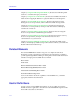
Chapter 1 Introduction How to use this guide; related guides; useful definitions; software conventions; getting help Welcome to the Generic SNMP User’s Guide. This guide is a reference for using NetSight Element Manager to manage and control any SNMP-compliant devices on your network. Using the Generic SNMP User’s Guide This guide contains information about software functions which are accessed directly from the Generic SNMP icon or the System Group option available from the Device menu.
Introduction Chapter 7, Using the IP Routing Table Window, discusses the IP Routing Table and how to route data through your network. Chapter 8, Using the Net to Media Table, discusses the IP Address Translation Table used for mapping IP addresses to physical addresses for IP datagrams. Chapter 9, Viewing ICMP Group Statistics, discusses the Internet Control Message Protocol Group window, which summarizes ICMP message traffic.
Introduction Active open A sequence of events occurring when an entity using an application protocol of the Internet suite (such as SMTP—the E-mail protocol; FTP—File Transfer Protocol; or Telnet—terminal service protocol) directs the Transmission Control Protocol to establish a connection over the physical medium with another user(s) of the application’s particular service. See Transmission Control Protocol (TCP), page 1-6, for more information.
Introduction Therefore, a site’s core gateway must have routing information on all networks available within the autonomous site, and must be able to pass reachability (of other Internet sites) information (using EGP) to each network gateway in that site. Flags The control bits indicating special functions for a TCP segment; for example, if the datagram is allowed to be fragmented, and if so, whether other later fragments exist.
Introduction Maximum transmission unit (MTU) The largest amount of user-data (e.g. the largest size of an IP datagram) that can be sent in a single frame on a particular medium. Passive open A sequence of events occurring when an entity using an application protocol of the Internet suite (e.g., SMTP, FTP, SNMP, or Telnet) informs the Transmission Control Protocol that it is willing to accept a connection to another user of the application’s particular service.
Introduction Subnet A physical network within the IP network. Subnet mask A 32-bit quantity (four binary octets) that filters a destination IP address to determine whether it exists on the source IP’s subnetwork and therefore can be reached directly, or must be forwarded through a gateway or router. In the mask, all bits in the source IP address that correspond to its network portion (both site and subnet identifying bits) are set to 1, and all bits that correspond to the host portion are set to 0.
Introduction Using the Mouse This document assumes you are using a Windows-compatible mouse with two buttons; if you are using a three-button mouse, you should ignore the operation of the middle button when following procedures in this document. Procedures within the NetSight Element Manager document set refer to these buttons as follows: Left Mouse Button Right Mouse Button Figure 1-1.
Introduction • Dragging means to move the mouse pointer across the screen while holding the mouse button down. It is often used for drag-and-drop operations to copy information from one window of the screen into another, and to highlight editable text. Common Generic SNMP Window Fields Similar descriptive information is displayed in text boxes at the top of most device-specific windows in NetSight Element Manager, as illustrated in Figure 1-2. System Description MAC Address IP Address Figure 1-2.
Introduction An OK, Set, or Apply button appears in windows that have configurable values; it allows you to confirm and SET changes you have made to those values. In some windows, you may have to use this button to confirm each individual set; in other windows, you can set several values at once and confirm the sets with one click on the button. The Help button brings up a Help window with information specific to the current window. For more information, see Getting Help, page 1-9.
Introduction Getting Help from the Global Technical Assistance Center If you need technical support related to NetSight Element Manager, contact the Global Technical Assistance Center via one of the following methods: By phone: (603) 332-9400 24 hours a day, 365 days a year By fax: (603) 337-3075 By mail: Enterasys Technical Support 35 Industrial Way Rochester, NH 03867 By e-mail: support@enterasys.com FTP: ftp.ctron.com (134.141.197.
Chapter 2 System Group The System Group window; using the Other Groups menu The System Group window provides basic information about the type of device currently being monitored, including the System Object ID and Uptime, as well as administrative information, including the device’s name, location, contact person, and the level of Open Systems Interconnection (OSI) services. You can access all other Generic SNMP windows from the System Group window.
System Group The System Group window displays the following fields: Object ID Displays the unique identifier of the device being managed. This value is allocated within the SMI enterprises subtree (1.3.6.1.4.1). Uptime Displays the amount of time that the device has been running since the network management portion of the system was last initialized. This is converted from hundredths of a second (as stored in the device MIB) into a more useful days, HH:MM:SS format.
System Group Figure 2-3. Contact Text Box b. Type in the new contact information in the text box; then click on OK. 2. To modify the Name field: a. Click the I-bar cursor ( ) to the right of the Name field. The Name text box opens, Figure 2-4. Figure 2-4. Name Text Box b. Type in the new name in the text box; then click on OK. 3. To modify the location field: a. Click on the I-bar cursor ( ) to the right of the Location field. The Location text box opens, Figure 2-5. Figure 2-5. Location Text Box b.
System Group Figure 2-6. Other Group Menu To access the Other Groups drop-down menu via the System Group window: 1. Click on the Other Groups button. The Other Groups drop-down menu displays, as shown in Figure 2-6. Non-supported options will be grayed-out. 2. Click on the desired option. The appropriate window opens.
Chapter 3 Viewing the Interface Group Viewing interface statistics; using the Admin/Status option and the Last Change field The Interface Group window displays statistics for each interface on the device. The port type is displayed for each interface along with the statistics associated with that interface. Use the scroll bar to display the other available interfaces; the interface number and the total number of interfaces on the device are displayed above the scroll bar (e.g., 1 of 27).
Viewing the Interface Group Figure 3-1. Interface Group Window The following fields are non-statistical interface descriptions fields: Address The interface’s physical address (ifPhysAddr) at the protocol layer immediately below the network layer in the protocol stack. For interfaces which do not have such an address (e.g., a serial line), this object should contain an octet string of zero length.
Viewing the Interface Group Last Change The Last Change field (bottom of the window) displays the date and the time since the system was last reinitialized. NOTE In accordance with Year 2000 compliance requirements, NetSight Element Manager displays and allows you to set all dates with four-digit year values. Viewing Statistics The following statistics are collected from received and transmitted packets.
Viewing the Interface Group Unknown Protocol (Received Packets only) The number of packets received via the interface which were discarded because of an unknown or unsupported protocol, according to the ifInUnknownProtos. Transmit Queue Size (Transmitted Packets only) The length of the output packet queue (in packets), according to the ifOutQLen.
Chapter 4 Using the Address Translation Table The Address Translation Table window; editing the Address Translation Table The Address Translation Table utilizes ARP (Address Resolution Protocol) to translate IP addresses into Physical addresses. ARP is used to achieve mapping between IP addresses which are 32 bits in length and Physical addresses which are 48 bits in length.
Using the Address Translation Table Figure 4-1. Address Translation Table Window The display panel (upper section) of the Address Translation window lists the addresses associated with the interface. The Values set for section lets you add and modify entries in the panel. Interface Index The network interfaces on which this system can send and receive IP datagrams. Physical Address The media dependent MAC addresses that have been detected in datagrams processed through the indicated Interface Index.
Using the Address Translation Table Editing the Address Translation Table You can modify existing entries in, or add new entries to the Address Translation Table. Modifying Entries in the Address Translation Table By modifying an entry in the Address Translation Table you will change the mapping that was discovered by the ARP process. 1. Click on an entry in the Address Translation Table.
Using the Address Translation Table 4-4
Chapter 5 Viewing IP Group Statistics The IP Group window; using the Time To Live option The Internet Protocol (IP) is the protocol used in the Internet layer. Each IP datagram contains identifying information such as the datagram’s originator, the datagram’s length, the format used (version), and the quality of service. Each medium has a maximum size data field used to encapsulate an IP datagram (Maximum Transmit Unit or MTU).
Viewing IP Group Statistics Figure 5-1. IP Group Window Forwarding State Displays whether this entity is acting as an IP gateway in respect to the forwarding of datagrams received by — but not addressed to — this entity, according to the ipForwarding. IP gateways forward datagrams; IP hosts do not (except those source-routed via the host). For some managed nodes, this object may take on only a subset of the values possible.
Viewing IP Group Statistics datagrams, this counter includes datagrams discarded because the destination address was not a local address. This field displays the ipInAddrErrors. Forwarded The number of received datagrams for which this entity was not their final IP destination, as a result of which an attempt was made to find a route to forward them to that final destination.
Viewing IP Group Statistics No Route The number of IP datagrams discarded because no route could be found to transmit them to their destination. This counter includes packets counted in ipForwDatagrams which meet this ‘no-route’ criterion, and any datagrams a host cannot route because all of its default gateways are down. This field displays the ipOutNoRoutes.
Viewing IP Group Statistics Setting the Time To Live Option When a device transmits an IP datagram, it sets the amount of time, in seconds, the datagram is allowed to exist, by setting the Time-To-Live (TTL) field located in the datagram’s header. This eliminates the possibility that a datagram could travel around a network forever. If the TTL timer expires before the datagram reaches its destination, the datagram is discarded and an error message is returned to the original sending device.
Viewing IP Group Statistics 5-6
Chapter 6 Viewing the IP Address Table The IP Address Table window The IP Address Table displays the IP Addresses and the subnet masks for each of the device’s interfaces. In addition, you can see whether network broadcasts will be sent with 1s or 0s in the host portion of the IP Address, and the maximum size fragment that can be reassembled. To open the IP Address Table window from the System Group window: 1. Click on the Other Groups window. The Other Groups drop-down menu displays. 2.
Viewing the IP Address Table The display panel of the IP Address Table window contains address information for each entry in the table. If there are more entries in the IP Address Table than can fit in the display panel, scroll bars displays so that you can view the remaining entries in the table. Interface Index The number of each interface on which this system can send and receive IP datagrams. IP Address The addressing information for one of this entity’s IP addresses, according to the ipAddrEntry.
Chapter 7 Using the IP Routing Table Window IP Routing Table window; modifying the routing information; The IP Routing Table provides a way for devices to exchange data. Your local IP device must determine the next “hop” or stop on the data route. If the destination is on the same IP network, then the next hop is the destination IP address. Otherwise, the next stop is a router (gateway) on the same IP network as the local device. The router is determined to be “closer” to the destination device.
Using the IP Routing Table Window Figure 7-1. IP Routing Table Window The IP Routing Table displays the following fields: Destination The destination IP address of this route, according to the ipRouteDest. An entry with a value of 0.0.0.0 is considered a default route. Multiple routes to a single destination can appear in the table, but access to such multiple entries is dependent on the table-access mechanisms defined by the network management protocol in use.
Using the IP Routing Table Window Route Mask Indicates the mask to be logical-ANDed with the destination address before being compared to the value in the ipRouteDest field, according to the ipRouteMask. For those systems that do not support arbitrary subnet masks, an agent constructs the value of the ipRouteMask by determining whether the value of the corresponding ipRouteDest field belongs to a class-A, B, or C network, and then uses one of the following: Mask 255.0.0.0 255.255.0.0 255.255.255.
Using the IP Routing Table Window Route Info A reference to MIB definitions specific to the particular routing protocol which is responsible for this route, as determined by the value specified in the route’s ipRouteProto value. If this information is not present, its value should be set to the OBJECT IDENTIFIER {0,0}, which is a syntactically valid object identifier, and any conformant implementation of ASN.1 and BER must be able to generate and recognize this value. This field displays the ipRouteInfo.
Using the IP Routing Table Window Modifying Entries in the IP Routing Table 1. Click in the Destination field, enter the desired destination IP address. 2. Click in the Next Hop field, enter the IP address that you want to specify as the next hop of the route. 3. Click in the Route Metrics field(s), enter the desired metric value(s). 4. Click the desired option in the Route Type section. 5. Click Apply to accept the changes, or Cancel to exit the IP Routing Table window without saving changes.
Using the IP Routing Table Window 7-6
Chapter 8 Using the Net to Media Table The Net To Media Table window; modifying an entry The Net to Media Table is used by MIB-II devices to map IP addresses to physical addresses when transmitting an IP datagram for devices on each network segment directly connected to the monitored device. The table includes the media type for each port interface, as well as the map type through which the table entry is obtained. MIB-I devices do not support the Net to Media Table.
Using the Net to Media Table The display panel (top section) of the Net to Media Table displays address information for the associated interface. The Values set for section lets you modify entries in the display panel and make static entries to the ARP cache. Interface Index The interface on which this entry’s equivalence is effective, according to the ipNetToMediaIfIndex. The interface identified by a particular value of this index is the same interface as identified by the same value of ifIndex.
Using the Net to Media Table 2. Enter the desired changes in the Physical Addr field within the Values set for area. 3. Click on the option button corresponding to the way you want that entry mapped into the database (other, invalid, dynamic, or static). Selecting invalid as the mapping type disables the selected translation entry. 4. Click Set. Status information displays above the command buttons and a confirmation window opens; if the set succeeded, the changes displays in the list.
Using the Net to Media Table 8-4
Chapter 9 Viewing ICMP Group Statistics The ICMP Group window ICMP (Internet Control Message Protocol) is the Internet Protocol mechanism used by network devices to determine if a destination is reachable and to notify other devices about delivery problems. Using PING (Packet Internet Groper), an ICMP echo request packet is sent to an IP address and awaits a reply.
Viewing ICMP Group Statistics Figure 9-1. ICMP Group Window The ICMP Group window displays the following message statistics: ICMP Received Message Statistics Total Messages The total number of ICMP messages which the entity received, according to the icmpInMsgs. This counter includes all those counted by icmpInErrors. Errors The number of ICMP messages which the entity received but determined as having ICMP-specific errors (bad ICMP checksums, bad length, etc.), according to the icmpInErrors.
Viewing ICMP Group Statistics Time Exceeded The number of ICMP Time Exceeded messages received, according to the icmpInTimeExcds. When a device discards a datagram because the time-to-live counter (hop count) reached zero, or because the reassembly counter expired while waiting for fragments, a router sends a time exceeded message to the station that transmitted the original datagram.
Viewing ICMP Group Statistics Address Mask Request The number of ICMP Address Mask Request Messages received, according to the icmpInAddrMasks. Address Mask Reply The number of ICMP Address Mask Reply messages received, according to the icmpInAddrMaskReps. To determine the network subnet mask, a machine can issue an address mask request, either targeted to a specific address or a broadcast to the entire network. A responding machine includes the network subnet mask in an address mask reply.
Viewing ICMP Group Statistics datagram. If the timer expires before all fragments are received, the station discards the fragments it has already received, and transmits a time exceeded message. Parameter Problem The number of ICMP Parameter Problem messages sent, according to the icmpOutParmProbs. A parameter problem message indicates that a datagram was discarded due to a problem not covered by any of the previous messages.
Viewing ICMP Group Statistics Address Mask Reply The number of ICMP Address Mask Reply messages sent, according to the icmpOutAddrMaskReps. To determine the network subnet mask, a device can issue an address mask request, either targeted to a specific address or a broadcast to the entire network. A responding device includes the network subnet mask in an address mask reply.
Chapter 10 Viewing TCP Group Information The TCP Group window The Transmission Control Protocol (TCP) is often called reliable stream transport service because it is based on a connection between two nodes. Like IP, TCP’s purpose is to transfer data between applications. TCP segments, the basic unit of data transfer within TCP, are carried within IP datagrams; usually, each TCP segment travels across the internet within a single IP datagram. Unlike IP, TCP ensures that the data arrives at its destination.
Viewing TCP Group Information Figure 10-1. TCP Group Window The left portion of the TCP Group window displays statistics about TCP circuits. The right portion shows the current active connections. TCP Statistics Retransmit Algorithm The algorithm used to determine the timeout value for retransmitting unacknowledged octets, according to the tcpRtoAlgorithm.
Viewing TCP Group Information Rto. Max. (Retransmit time out Maximum) The maximum value permitted by a TCP implementation for the retransmission timeout (measured in milliseconds) according to the tcpRtoMax. More refined semantics for objects of this type depend upon the algorithm used to determine the retransmission timeout. In particular, when the timeout algorithm is rsre (3), an object of this type has the semantics of the UBOUND quantity described in RFC 793.
Viewing TCP Group Information Closed Connections The number of times the TCP connections have made a direct transition to the CLOSED state from either the ESTABLISHED state or the CLOSE-WAIT state, according to the tcpEstabResets. Open Connections The number of TCP connections in which the current state is either ESTABLISHED or CLOSE-WAIT, according to the tcpCurrEstab. Segments Received The total number of segments received, including those received in error, according to the tcpInSegs.
Viewing TCP Group Information Active Connections Table The following information is displayed for each Active Connection in the TCP Group window. If there is no TCP connection at the device, “No Connection” displays in the connection State field. State The state of this TCP connection, according to the tcpConnState.
Viewing TCP Group Information Remote Port The remote port number for this TCP connection, according to the tcpConnRemPort. Most TCP applications use a set of well-known ports. Well-known ports are always 256 or lower. A few examples of well-known port numbers are 21 for FTP, 23 for Telnet, and 53 for domain name server. Other port numbers are available for assignment as needed. TIP 10-6 The Prev and Next buttons let you scroll through the connections on your device, and review their state.
Chapter 11 Viewing UDP Group Information The UDP Group window The User Datagram Protocol (UDP) is the piece of the TCP/IP protocol suite that deals with getting a datagram from an application running on one host to an application running on a different host. UDP is able to choose the correct process on a host by delivering the datagram to a specific port. A port is nothing more than a queue, assigned by the operating system and used by a specific process to send and receive datagrams.
Viewing UDP Group Information Figure 11-1. UDP Group Window—MIB I and MIB II The UDP Group window displays statistics about UDP connections. The Listener Table (bottom portion) displays the current UDP connections (MIB II only). UDP Group Statistics Receive Datagrams The total number of UDP datagrams delivered to UDP users, according to the udpInDatagrams. A UDP user is the protocol port assigned by the operating system to a particular application.
Viewing UDP Group Information UDP Listener Table The UDP Listener Table, available for MIB-II devices, displays a list of the active UDP ports on the device. Local IP Address In the case of a UDP listener which is willing to accept datagrams for any IP interface associated with the node, the value 0.0.0.0 is used. This field displays the udpLocalAddress.
Viewing UDP Group Information 11-4
Chapter 12 Viewing EGP Group Information The EGP Group window; displaying the EGP Group Neighbor Table Detail window; using the Event Trigger button The Exterior Gateway Protocol (EGP) controls how gateways on neighboring autonomous systems exchange routing information; it tells an IP network device about the reachability of other IP networks. It does not provide the entire route; but merely indicates the route a datagram would need to follow to reach a given network.
Viewing EGP Group Information Figure 12-1. EGP Group Window—MIB II The EGP Group window displays the following statistics: Receive Messages The number of EGP messages received without errors, according to egpInMsgs. Receive Errors The number of EGP messages received that proved to be in error, according to egpInErrors. Transmit Messages The total number of locally generated EGP messages, according to egpOutMsgs.
Viewing EGP Group Information State The EGP state of the local system with respect to this entry’s EGP neighbor, according to egpNeighState. Each EGP state is represented by a value that is one greater than the numerical value associated with the EGP peer.
Viewing EGP Group Information The EGP Group Neighbor Table Detail window displays the following statistics: Address The IP address of the entry’s EGP neighbor, according to egpNeighAddr. State The EGP state of the local system with respect to this entry’s EGP neighbor, according to the egpNeighState. Each EGP state is represented by a value that is one greater than the numerical value associated with the EGP peer.
Viewing EGP Group Information Hello The interval between EGP Hello command retransmissions (in hundredths of a second), according to egpNeighIntervalHello. This represents the t1 timer as defined in RFC 904. The t1 timer controls Request (initiate communications with a neighbor), Hello (periodic reachability updates), and Cease (sever communications with a neighbor) transmissions. Poll The interval between EGP poll command retransmissions (in hundredths of a second), according to egpNeighIntervalPoll.
Viewing EGP Group Information 12-6 Displaying the EGP Group Neighbor Table Detail Window
Chapter 13 Viewing SNMP Group Information The SNMP Group window; disabling and enabling authentication failure traps The Simple Network Management Protocol (SNMP) facilitates communication between a management application, like NetSight Element Manager, and a network device, through the use of Protocol Data Units (PDUs). A network manager requests data by issuing a Get-Request or Get-Next Request PDU, or writes a new value into the device’s MIB by issuing a Set-Request PDU.
Viewing SNMP Group Information Figure 13-1. SNMP Group Window The SNMP Group Window displays a summary of PDU activity, and lets you enable or disable the device’s ability to issue authentication failure traps. SNMP Received Statistics The fields described below represent counters which record various categories of received SNMP messages. Messages The total number of messages delivered to the SNMP entity from the transport service.
Viewing SNMP Group Information Bad Community Names The total number of messages delivered to the SNMP protocol entity which used a SNMP community name not known to the entity, according to the snmpInBadCommunityNames. An SNMP Get or Set request must be accompanied by a valid community name.
Viewing SNMP Group Information readOnly Errors The total number of valid SNMP PDUs which were delivered to the SNMP protocol entity and for which the value of the error-status field is ‘readOnly’. It should be noted that it is a protocol error to generate a SNMP PDU which contains the value ‘readOnly’ in the error-status field, as such this object is provided as a means of detecting incorrect implementation of the SNMP. This field displays the snmpInReadOnlys.
Viewing SNMP Group Information Total Trap PDUs The total number of SNMP Trap PDUs which have been accepted and processed by the SNMP protocol entity, according to snmpInTraps. This counter represents traps received by a device. A device can not receive traps unless the sending device’s community names table is set up so that traps are enabled and pointed toward the receiving station’s IP address.
Viewing SNMP Group Information Total Get-Next PDUs The total number of SNMP Get-Next PDUs which have been generated by the SNMP protocol entity, according to the snmpOutGetNexts. Total Set-Request PDUs The total number of SNMP Set-Request PDUs which have been generated by the SNMP protocol entity, according to the snmpOutSetRequests. Total Get-Response PDUs The total number of SNMP Get-Response PDUs which have been generated by the SNMP protocol entity, according to the snmpOutGetResponses.
Index A Active open 1-3 Active Opens 10-3 Address 3-2, 12-2, 12-4 Address Errors 5-2 Address mask 1-3 Address Mask Reply 9-4, 9-6 Address Mask Request 9-4, 9-5 Address Resolution Protocol (ARP) 1-3 Address Translation Table 4-1 adding entries 4-3 editing 4-3 Admin Status 3-4 setting the Admin Status 3-4 AS 12-4 AS Number 12-2 Authentication Failure Traps 13-6 Datagrams Reassembled 5-4 Delivered 5-3 Destination 7-2 Destination Unreachable 9-2, 9-4 Device View window 2-1 Discarded 3-3, 5-3, 5-4 Dns 12-4 E
Index I ICMP Group window 9-1 Incoming Seg Errors 10-4 InErrs 12-3, 12-4 InMsgs 12-4 Interface Group window 3-1 statistics 3-3 Interface Index 4-2, 6-2, 8-2 Interface Type 3-2 Internet 1-4 Internet Control Message Protocol (ICMP) 1-4 Internet Protocol (IP) 1-4, 5-1 IP Address 1-1, 1-8, 4-2, 6-2, 8-2 IP Address Table window 6-1 IP Group window 5-1 IP Routing Table 7-1 window 7-1 L Last Change 3-3 Local Address 10-5 Local IP Address 11-3 Local Port 10-5 Location 2-2 M MAC address 1-8 Management Information
Index SNMP 1-5, 13-1 Socket 1-5 Source Quench 9-3, 9-5 Specific Mib Def.
Index Index-4