
Instruction Manual

6 Product Overview VH-2402S
Rear Panel
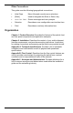
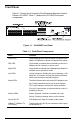
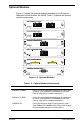
Figure 1-3 shows the VH-2402S rear panel and Table 1-3 defines the rear
panel components.
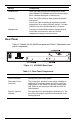
Figure 1-3. VH-2402S Rear Panel
Table 1-3. Rear Panel Components
1000Base-LX
Ports: One fiber port using SC connectors for uplink.
(See 100Base-FX/1000Base-SX/LX Fiber Ports on page
28 for a detailed
description of these ports.)
Stacking
Ports: Two SCSI II ports for stack uplink and downlink
connections.
One 32 cm cable included with the stacking module
and both the 32 cm cable (9380142) and the 1 m cable
(9380143) can be ordered separately, if required.
Management Console port: Male DB-9 connector configured as a
null modem connection for serial out-of-band
management using the console menus.
Name Function
Power Connector Provides AC power to the switch.
Redundant Power
Connector
This connector is provided for the option of adding an
additional DC redundant power unit (RPU) which can
supply power to the switch if its primary power supply
fails. (Refer to the manual provided with the RPU for
further details.)
Slots for Optional
Modules
The upper slot is for the Management Module only. The
two lower slots support optional media modules or the
Stacking Module.
Module Components