VERTICAL HORIZON VH-2402S FAST ETHERNET SWITCH MANAGEMENT GUIDE 9033645-01
Notice Only qualified personnel should perform installation procedures. NOTICE Enterasys Networks reserves the right to make changes in specifications and other information contained in this document without prior notice. The reader should in all cases consult Enterasys Networks to determine whether any such changes have been made. The hardware, firmware, or software described in this manual is subject to change without notice.
Notice ii 9033645-01
TABLE OF CONTENTS 1. MANAGEMENT OVERVIEW . . . . . . . . . . . . . . . . . . . . . . . . . . . . . . . . . . . . . . 1 Configuration Options . . . . . . . . . . . . . . . . . . . . . . . . . . . . . . . . . . . . . . . 1 Required Connections . . . . . . . . . . . . . . . . . . . . . . . . . . . . . . . . . . . . . . 1 Console Port (Out-of-Band) Connections . . . . . . . . . . . . . . . . . . . . 1 Remote Management via the Console Port . . . . . . . . . . . . . . . . . . . 2 In-Band Connections . . . . . .
Displaying the Unicast Address Table . . . . . . . . . . . . . . . . . . . . . Displaying the IP Multicast Registration Table . . . . . . . . . . . . . . . Configuring Static Unicast Addresses. . . . . . . . . . . . . . . . . . . . . . Resetting the System . . . . . . . . . . . . . . . . . . . . . . . . . . . . . . . . . . . . . . Logging Off the System . . . . . . . . . . . . . . . . . . . . . . . . . . . . . . . . . . . . 62 63 64 65 65 3. CONFIGURING & MONITORING THE SWITCH . . . . . . . . . . . . . .
Remapping Network Topology . . . . . . . . . . . . . . . . . . . . . . . . . . . 88 APPENDIX B. VIRTUAL LANS (VLANS) . . . . . . . . . . . . . . . . . . . . . . . . . . . . . 91 VLANs and Frame Tagging . . . . . . . . . . . . . . . . . . . . . . . . . . . . . . . . . 91 VH-2402S VLAN Configuration. . . . . . . . . . . . . . . . . . . . . . . . . . . . . . . 92 Assigning Ports to VLANs . . . . . . . . . . . . . . . . . . . . . . . . . . . . . . . 92 Forwarding Tagged/Untagged Frames . . . . . . . . . . . . .
vi Table of Contents VH-2402S
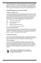
1. MANAGEMENT OVERVIEW Configuration Options For advanced management capability, the VH-SMGMT Vertical Horizon Management Module provides a menu-driven system configuration program. This program can be accessed by a direct or modem connection to the serial port on the Management Module (out-of-band), or by a Telnet connection over the network (in-band). The Management Module is based on SNMP (Simple Network Management Protocol).
When attaching to a PC, set terminal emulation type to VT100, specify the port used by your PC (i.e., COM 1~4), and then set communications to 8 data bits, 1 stop bit, no parity, and 19200 bps (for initial configuration). Also be sure to set flow control to “none.” (Refer to “Configuring the Serial Port” on page 19 for a complete description of configuration options.
In-Band Network Connection The on-board configuration program can be accessed using Telnet from any computer attached to the network. The switch and stack can also be managed by any computer using a Web browser (Internet Explorer 4.0 or above, or Netscape Navigator 4.0 or above), or from a network computer using network management software.
4 Management Overview VH-2402S
2. VH-2402S USER INTERFACE Overview Access is gained to the console menus by connecting a terminal to the console port (with a direct cable connection or over modems), or using Telnet to access the Management Module over the network. These menus allow you to reconfigure the switch, as well as to monitor the status and performance of the switch or the attached stack. The menus have a layout similar to the sample Main Menu shown in Figure 2-1.
User Access Once a direct connection to the serial port or a Telnet connection is established, the login screen for the on-board configuration program appears. You may need to press Enter a few times to display the screen. The default user names are “admin” and “guest,” with no passwords. The administrator has Read/Write access, which allows you to read and modify switch information.
Factory Defaults Table 2-1 lists the default settings for switch configuration parameters. Each parameter can be changed via the console menus or Telnet. Table 2-1.
Parameter Default Value Virtual LANs Acceptable VLAN Frame Type All Configurable PVID Tagging Yes GVRP Disabled Untagged VLAN Group Assignment 1 VLAN Ingress Filtering False VLAN Learning SVL 8 VH-2402S User Interface VH-2402S
Main Menu The Main Menu is the first screen seen after successfully logging into the system. Figure 2-2 shows the Main Menu and the accompanying table describes the Main Menu. Vertical Horizon Local Management -- VH-2402S Main Menu System Information Menu... Management Setup Menu... Device Control Menu... Network Monitor Menu... System Restart Menu... Exit Use or arrow keys to move. to select. Figure 2-2.
Selection Description Device Control Menu Port Configuration Enables any port, enables/disables flow control, and sets communication mode to auto-negotiation, full duplex or half duplex. Port Information Displays operational status, including link state, flow control method, and duplex mode. Spanning Tree Configuration Enables Spanning Tree Algorithm; also sets parameters for hello time, maximum message age, switch priority, and forward delay; as well as port priority and path cost.
Selection Description IP Multicast Registration Table Displays all the multicast groups active on this switch, including multicast IP addresses and corresponding VLAN IDs. Static Unicast Address Table Configuration Used to manually configure host MAC addresses in the unicast table. System Restart Restarts system with options to use POST, or to retain factory defaults, IP settings, or user authentication settings. Exit Exits the configuration program.
Displaying System Information Use the System Information screen to display descriptive information about the switch, or for quick system identification as shown in the following figure and table. Vertical Horizon Local Management -- VH-2402S System Information System Description : Vertical Horizon VH-2402S System Object ID : 1.3.6.1.4.1.52.3.9.1.10.
Displaying Switch Version and Module Information Use the Switch Information screen to display hardware/firmware version numbers for the main board and agent module, as well as the power status and modules plugged into the system. Vertical Horizon Local Management -- VH-2402S Switch Information : Unit 1 Main Board Hardware Version : Firmware Version : Serial Number : Port Number : Internal Power Status : Redundant Power Status : Expansion Slot 1 : Expansion Slot 2 : V3.0 V1.
Management Setup Menu After initially logging onto the system, adjust the communication parameters for your console to ensure a reliable connection (Serial Port Configuration). Specify the IP addresses for the agent module (Network Configuration / IP Configuration), and then set the Administrator and User passwords (Console Login Configuration). Remember to record them in a safe place.
Changing the Network Configuration Use the Network Configuration menu to set the bootup option, configure the switch’s Internet Protocol (IP) parameters, enable the on-board Web Agent, or to set the number of concurrent Telnet sessions allowed. The screen shown below is described in the following table. Vertical Horizon Local Management -- VH-2402S Network Configuration IP Configuration ... IP Connectivity Test (Ping) ... HTTP Configuration ...
IP Configuration Use the IP Configuration screen to set the bootup option, or configure the switch’s IP parameters. The screen shown below is described in the following table. Vertical Horizon Local Management -- VH-2402S Network Configuration: IP Configuration Interface Type IP Address Subnet Mask Gateway IP IP State : Ethernet : 10.1.0.1 : 255.255.0.0 : 10.1.0.254 : USER-CONFIG Use or arrow keys to move, other keys to make changes. Figure 2-8.
Parameter Default Description BOOTP Get IP - IP is enabled but will not function until a BOOTP reply has been received. BOOTP requests will be periodically broadcast by the switch in an effort to learn its IP address. (BOOTP values can include the IP address, default gateway, and subnet mask.) IP Connectivity Test (Ping) Use the IP Connectivity Test to see if another site on the Internet can be reached. The screen shown below is described in the following table.
HTTP Configuration Use the HTTP Configuration screen to enable/disable the on-board Web agent, and to specify the TCP port that will provide HTTP service. The screen shown below is described in the following table. Vertical Horizon Local Management -- VH-2402S Network Configuration : HTTP Configuration HTTP Server : ENABLED HTTP Port Number : 80 Use or arrow keys to move, to scroll options. Figure 2-10.
Configuring the Serial Port You can access the on-board configuration program by attaching a VT100 compatible device to the switch’s serial port. (For more information on connecting to this port, see “Required Connections” on page 1.) The communication parameters for this port can be accessed from the Serial Port Configuration screen shown below and described in the following table.
Assigning SNMP Parameters Use the SNMP Configuration screen to display and modify parameters for the Simple Network Management Protocol (SNMP). The switch includes an on-board SNMP agent which monitors the status of its hardware, as well as the traffic passing through its ports. A computer attached to the network, called a Network Management Station (NMS), can be used to access this information. Access rights to the on-board agent are controlled by community strings.
Configuring Community Names The following figure and table describe how to configure the community strings authorized for management access. Up to 5 community names may be entered. Vertical Horizon Local Management -- VH-2402S SNMP Configuration : SNMP Communities Community Name 1. public 2. private 3. 4. 5. Access Status READ ONLY ENABLED READ/WRITE ENABLED Use or arrow keys to move, other keys to make changes. Figure 2-13.
Configuring IP Trap Managers The following figure and table describe how to specify management stations that will receive authentication failure messages or other trap messages from the switch. Up to 5 trap managers may be entered. Vertical Horizon Local Management -- VH-2402S SNMP Configuration : IP Trap Managers IP Address 1. 10.1.0.23 2. 3. 4. 5. Community Name Status public DISABLED Use or arrow keys to move, other keys to make changes. Figure 2-14.
Console Login Configuration Use the Management Setup: Console Login Configuration to restrict management access based on specified user names and passwords, or to set the invalid password threshold and timeout. There are only two user types defined, ADMIN (Administrator) and GUEST, but you can set up to five different user names and passwords. Only Administrators have write access for parameters governing the switch.
Downloading System Software Using TFTP Protocol to Download Over the Network Use the TFTP Download menu to load software updates into the switch. The download file should be an VH-2402S file from Enterasys; otherwise the agent will not accept it. The success of the download operation depends on the accessibility of the TFTP server and the quality of the network connection. After downloading the new software, the agent will automatically restart itself.
Saving the System Configuration Use the Configuration Save & Restore menu to save the switch configuration settings to a file on a TFTP server. The file can be later downloaded to the switch to restore the switch’s settings. The success of the operation depends on the accessibility of the TFTP server and the quality of the network connection. Parameters shown on this screen are indicated in the following figure and table.
Configuring Management Access Use the Management Configuration menu to define which VLAN has management access to the switch. Parameters shown on this screen are indicated in the following figure and table. Vertical Horizon Local Management -- VH-2402S Management Configuration Management VLAN : ALL VLAN :1 Use or arrow keys to move, to scroll options. Figure 2-18.
Configuring the Switch The Device Control menu is used to control a broad range of functions, including port configuration, Spanning Tree support for redundant switches, port mirroring, multicast filtering, and Virtual LANs. Each of the setup screens provided by these configuration menus is described in the following sections. Vertical Horizon Local Management -- VH-2402S Device Control Menu Port Configuration ... Port Information ... Spanning Tree Configuration ... Spanning Tree Information ...
Selection Description 802.1Q VLAN Base Information Displays basic VLAN information, such as VLAN version number and maximum VLANs supported. 802.1Q VLAN Current Table Information Displays VLAN groups and port members. 802.1Q VLAN Static Table Configuration Configures VLAN groups via static assignments, including setting port members, or restricting ports from being dynamically added to a port by the GVRP protocol.
Configuring Port Parameters Use the Port Configuration menus to set or display communication parameters for any port or module on the switch. Vertical Horizon Local Management -- VH-2402S Port Configuration : Unit 1 Port 1-12 Port Type Admin Flow Speed and Control Duplex ------------------------------------------------------------------------1. 10/100TX ENABLED ENABLED 10-HALF 2. 10/100TX ENABLED ENABLED 100-FULL 3. 10/100TX ENABLED ENABLED AUTO 4. 10/100TX ENABLED ENABLED AUTO 5.
Viewing the Current Port Configuration The Port Information screen displays the port type, status, link state, and flow control in use, as well as the communication speed and duplex mode. To change any of the port settings, use the Port Configuration menu. The parameters shown in the following figure and table are for the RJ-45 ports.
Using the Spanning Tree Algorithm The Spanning Tree Algorithm can be used to detect and disable network loops, and to provide backup links between switches, bridges or routers. This allows the switch to interact with other bridging devices (that is, an STA-compliant switch, bridge or router) in your network to ensure that only one route exists between any two stations on the network. For a more detailed description of how to use this algorithm, refer to Appendix A, “Spanning Tree Concepts” on page 85.
Parameter Default Description Spanning Tree Protocol Enabled Enable this parameter to participate in an STA compliant network. Priority 32,768 Device priority is used in selecting the root device, root port, and designated port. The device with the highest priority becomes the STA root device. However, if all devices have the same priority, the device with the lowest MAC address will then become the root device. Enter a value from 0 - 65535.
Configuring STA for Ports or Modules The following figure and table describe STA configuration for ports or modules. (Note that the Spanning Tree Configuration screen for the expansion slots also indicates module type.
Parameter Default Description FastForwarding ENABLED This parameter is used to enable/disabled the Fast Spanning Tree mode for the port. In this mode, ports skip the Blocked, Listening and Learning states and proceed straight to Forwarding. FastForwarding enables end-node workstations and servers to overcome time-out problems when the Spanning Tree Algorithm is implemented in a network. Therefore, FastForwarding should only be enabled for ports that are connected to an endnode device.
Displaying the Current Bridge STA The parameters shown in the following figure and table describe the current Bridge STA Information. Vertical Horizon Local Management -- VH-2402S Spanning Tree Information : Bridge STA Information Priority Hello Time (in seconds) Max Age (in seconds) Forward Delay (in seconds) Hold Time (in seconds) Designated Root Root Cost Root Port Configuration Changes Topology Up Time : 32768 :2 : 20 : 15 :1 : 0.
Displaying the Current STA for Ports or Modules The parameters shown in the following figure and table are for port or module STA Information (Port 1-12, Port 13-24, Port 25-32). Vertical Horizon Local Management -- VH-2402S Spanning Tree Port Information : Unit 1 Port 1-12 Port Type Status Designated Designated Designated Cost Bridge Port ------------------------------------------------------------------------------------------------------1. 10/100TX FORWARDING 0 0.0000E800E800 128.3 2.
Parameter Description The rules defining port status are: • A port on a network segment with no other STA-compliant bridging device is always forwarding. • If two ports of a switch are connected to the same segment and there is no other STA device attached to this segment, the port with the smaller ID forwards packets and the other is blocked. • All ports are blocked when the switch is booted, then some of them change state to listening, to learning, and then to forwarding.
Using a Mirror Port for Analysis You can mirror traffic from any source port to a target port for real-time analysis. You can then attach a logic analyzer or RMON probe to the target port and study the traffic crossing the source port in a completely unobtrusive manner. When mirroring port traffic, note that the target port must be configured in the same VLAN and be operating at the same speed as the source port (see Configuring Virtual LANs on page 49).
Configuring Port Trunks Port trunks can be used to increase the bandwidth of a network connection or to ensure fault recovery. You can configure up five trunk connections (combining 2~4 ports into a fat pipe) between any two standalone VH-2402S switches, or up to 12 for an entire stack. However, before making any physical connections between devices, use the Trunk Configuration menu to specify the trunk on the devices at both ends.
You can use the Port Trunking Configuration screen set up port trunks as shown below: Vertical Horizon Local Management -- VH-2402S Port Trunking Configuration Trunk ID Status Member List 1 2 3 4 ------------- ------------- ---------------- ---------------- ---------------- ---------------------------Unit : Unit : Unit : Unit : Port : -Port : -Port : -Port : --- ------------ Unit : Port : -- Unit : Port : -- Unit : Port : -- Unit : Port : -- -- ------------ Unit : Port : -- Unit : Port : -- Unit
IGMP Multicast Filtering Multicasting is used to support real-time applications such as video conferencing or streaming audio. A multicast server does not have to establish a separate connection with each client. It merely broadcasts its service to the network, and any hosts which want to receive the multicast register with their local multicast switch/router.
Configuring IGMP This protocol allows a host to inform its local switch/router that it wants to receive transmissions addressed to a specific multicast group. You can use the IGMP Configuration screen to configure multicast filtering shown below: Vertical Horizon Local Management -- VH-2402S IGMP Configuration IGMP Status : DISABLED Act as IGMP Querier : DISABLED IGMP Query Count :2 IGMP Report Delay (Seconds) : 10 Use or arrow keys to move, to scroll options.
Configuring Broadcast Storm Control Use the Broadcast Storm Control Configuration screen to enable broadcast storm control for any port on the switch, as shown below: Vertical Horizon Local Management -- VH-2402S Broadcast Storm Control Configuration : Unit 1 Port 1-12 Broadcast control on all ports : [Enable] [Disable] Port Threshold Broadcast Control ------------------------------------------------------1 500 ENABLED 2 500 ENABLED 3 500 ENABLED 4 500 ENABLED 5 500 ENABLED 6 500 ENABLED 7 500 ENABLED 8 500
Configuring Bridge MIB Extensions The Bridge MIB includes extensions for managed devices that support Traffic Classes, Multicast Filtering and Virtual LANs.
Parameter Description Bridge Settings Traffic Class* Multiple traffic classes are supported by this switch as indicated under Bridge Capabilities. However, you can disable this function by setting this parameter to False. VLAN Learning As default this switch uses Shared VLAN Learning (SVL), whereby all ports share one VLAN filtering database. However, you can set the switch to use Independent VLAN Learning (IVL), where each port maintains its own filtering database.
Configuring Traffic Classes IEEE 802.1p defines up to 8 separate traffic classes. This switch supports Quality of Service (QoS) by using two priority queues, with weighted fair queuing for each port. You can use the 802.1P Configuration menu to configure the default priority for each port, or to display the mapping for the traffic classes as described in the following sections. Also, refer to Appendix C, “Class of Service” on page 95. . Vertical Horizon Local Management -- VH-2402S 802.
Port Priority Configuration The default priority for all ingress ports is zero. Therefore, any inbound frames that do not have priority tags will be placed in the low priority output queue. Default priority is only used to determine the output queue for the current port; no priority tag is actually added to the frame. You can use the 802.1P Port Priority Configuration menu to adjust default priority for any port as shown below: Vertical Horizon Local Management -- VH-2402S 802.
802.1P Port Traffic Class Information This switch provides two priority levels with weighted fair queuing for port egress. This means that any frames with a default or user priority from 0~3 are sent to the low priority queue “0” while those from 4~7 are sent to the high priority queue “1” as shown in the following screen: Vertical Horizon Local Management -- VH-2402S 802.
Configuring Virtual LANs You can use the VLAN configuration menu to assign any port on the switch to any of up to 256 LAN groups. In conventional networks with routers, broadcast traffic is split up into separate domains. Switches do not inherently support broadcast domains. This can lead to broadcast storms in large networks that handle a lot of IPX and NetBeui traffic. By using IEEE 802.
802.1Q VLAN Current Table Information This screen shows the current port members of each VLAN and whether or not the port supports VLAN tagging. Ports assigned to a large VLAN group that crosses several switches should use VLAN tagging. However, if you just want to create a small port-based VLAN for one or two switches, you can assign ports to the same untagged VLAN (page 53). The current configuration is shown in the following figure. Vertical Horizon Local Management -- VH-2402S 802.
802.1Q VLAN Static Table Configuration Use this screen to create a new VLAN or modify the settings for an existing VLAN. You can add/delete port members for a VLAN from any unit in the stack, or prevent a port from being automatically added to a VLAN via the GVRP protocol. (Also, note that all ports can only belong to one untagged VLAN. This is set to VLAN 1 by default, but can be changed via the Port Assignment VLAN Configuration screen on page 53.
For example, the following screen displays settings for VLAN 2, which includes tagged ports 1-6, and forbidden port 12. (Note that the dashed lines show that there are no switch units in this system other than Unit 1.) Vertical Horizon Local Management -- VH-2402S 1Q VLAN Static Table Configuration VID VLAN Name Status ------------------------------------------2 Active Unit 1. 2. 3. 4.
Port Assignment VLAN Configuration Use this screen to configure port-specific settings for IEEE 802.1Q VLAN features. Vertical Horizon Local Management -- VH-2402S Port Assignment VLAN Configuration Unit Port PVID 802.
Multicast Router Port Information You can use the Multicast Router Port Information screen to display the ports on this switch attached to a neighboring multicast router/switch for each VLAN ID.
Static Multicast Router Port Configuration You can use the Static Multicast Router Port Configuration screen to assign ports that are attached to a neighboring multicast router/switch.
IGMP Member Port Configuration You can use the IGMP Member Port Configuration screen to assign ports that are attached to hosts who want to receive a specific multicast service.
Port Security Configuration Use the Port Security Configuration screen to enable and configure port security for the switch. Port Security allows you to configure each port with a list of MAC addresses of devices that are authorized to access the network through that port.
Monitoring the Switch The Network Monitor Menu provides access to port statistics, RMON statistics, IP multicast addresses, and the static (unicast) address table. Each of the screens provided by these menus is described in the following sections. Vertical Horizon Local Management -- VH-2402S Network Monitor Menu Port Statistics ... RMON Statistics ... Unicast Address Table ... Multicast Address Registration Table ... IP Multicast Registration Table ... Static Unicast Address Table Configuration ...
Displaying Port Statistics Port Statistics display key statistics from the Ethernet-like MIB for each port. Error statistics on the traffic passing through each port are displayed. This information can be used to identify potential problems with the switch (such as a faulty port or unusually heavy loading). The values displayed have been accumulated since the last system reboot. Select the required stack unit, and port or module. The statistics displayed are indicated in the following figure and table.
Parameter Description Internal Mac Transmit Errors* The number of frames for which transmission failed due to an internal MAC sublayer transmit error. Carrier Sense Errors* The number of times that the carrier sense condition was lost or never asserted when attempting to transmit a frame. Frames Too Long The number of frames received that exceed the maximum permitted frame size. Internal Mac Receive Errors* The number of frames for which reception failed due to an internal MAC sublayer receive error.
Parameter Description Drop Events The total number of events in which packets were dropped due to lack of resources. Received Bytes Total number of bytes of data received on the network. This statistic can be used as a reasonable indication of Ethernet utilization. Received Frames The total number of frames (bad, broadcast and multicast) received. Broadcast Frames The total number of good frames received that were directed to the broadcast address. Note that this does not include multicast packets.
Displaying the Unicast Address Table The Address Table contains the MAC addresses and VLAN identifier associated with each port (that is, the source port associated with the address and VLAN), sorted by MAC address or VLAN ID. You can search for a specific address, clear the entire address table, or information associated with a specific address, or set the aging time for deleting inactive entries.
Displaying the IP Multicast Registration Table Use the IP Multicast Registration Table to display all the multicast groups active on this switch, including multicast IP addresses and the corresponding VLAN ID. Vertical Horizon Local Management -- VH-2402S IP Multicast Registration Table VID Multicast IP Unit Multicast Group Port Lists Learned by ------------------------------------------------------------------------------------------------1 225.1.1.1 1. 000000001100 110000000000 00 IGMP 2.
Configuring Static Unicast Addresses Use the Static Unicast Address Table Configuration screen to manually configure host MAC addresses in the unicast table. You can use this screen to associate a MAC address with a specific VLAN ID and switch port as shown below.
Resetting the System Select the System Restart Menu under the Main Menu to reset the management agent. The reset screen includes options as shown in the following figure and table. Vertical Horizon Local Management -- VH-2402S System Restart Menu Restart Option : POST Reload Factory Defaults Keep IP Setting Keep User Authentication : YES : NO : NO : NO [Restart] Use or arrow keys to move, to scroll options. Figure 2-51.
66 VH-2402S User Interface VH-2402S
3. CONFIGURING & MONITORING THE SWITCH Common Tasks The switch console menus allow you to modify default switch settings and configure the switch for network management. They also allow you to monitor switch performance and status. See Section 2, “VH-2402S User Interface,” for an overview of the menu hierarchy and a description of all menus. The following sections describe common tasks in setting up and operating the VH-2402S switch using the console menus.
Setting Password Protection The VH-2402S switch is factory-configured with administrator access rights to the console menus set to READ/WRITE. This setting allows anyone to use the console menus to modify any operational parameter. To protect the configuration of the switch from unauthorized modification, you should enable password protection to the console menus. To enter a password, do the following: 1. Select Management Setup Menu from the Main Menu and press [Enter]. 2.
Assigning an IP Address To assign an IP address to the switch, do the following: 1. Select Management Setup Menu from the Main menu. 2. Select Network Configuration and then IP Configuration. 3. Highlight the IP address field and enter the IP address. Press [Enter]. The IP address is now set. The subnet mask is automatically set to correspond to the class of the address entered. If a different mask is used on the network, higlight Subnet Mask and enter the appropriate mask.
Setting SNMP Management Access Access to the VH-2402S switch through SNMP is controlled by community names. The community names set for the switch must match those used by the SNMP management station for successful communication to occur. Access for community names can be set to READ/WRITE or READ ONLY access. The default “Public” community name allows READ ONLY access to the device via SNMP, whereas the default “Private” community name allows READ/WRITE access.
Configuring Port Mirroring You can mirror the traffic being switched on any port for the purposes of network traffic analysis and connection assurance. When Port Mirroring is enabled, one port becomes a monitor port for any other port within the stack. Note that the source and target ports must be configured within the same VLAN and be operating at the same speed. If the target port is operating at a lower speed, the source port will be forced to drop its operating speed to match that of the target port.
Downloading Via the Serial Port A serial download is the easiest method to upgrade the VH-2402S switch software, requiring the least amount of equipment and configuration. To download switch software via the serial port, do the following: 1. With the console port connected, reset the switch by powering the switch off and then on. 2. After the power-on hardware and software tests are complete, the system initialization screen displays the following message:.
server and the name of the upgrade file. To program the switch IP address, select the Management Setup Menu from the Main Menu screen, then select Network Configuration. To download switch software via TFTP, do the following: 1. Select Download Server IP Address from the TFTP Download Menu. 2. Enter the TFTP server IP address and press [Enter]. 3. Select Download Filename and enter the file name to be downloaded from the TFTP server.
Configuring Spanning Tree Parameters The VH-2402S switch supports the IEEE 802.1D Spanning Tree Protocol. This protocol allows redundant connections to be created between LAN segments for purposes of fault tolerance. Two or more physical paths between different segments can be created through the switch, with the Spanning Tree Protocol choosing a single path at any given time and disabling all others.
Configuring VLANs A virtual LAN (VLAN) is a group of devices on one or more LANs that are configured such that they can communicate as if they were attached to the same wire. Because VLANs are based on logical instead of physical connections, they are extremely flexible. The most fundamental benefit of VLAN technology is the ability to create workgroups based on function rather than on physical location or media. For further information, see Appendix B, “Virtual LANs (VLANs)” on page 91.
Configuring Port Operation You can configure switch ports for operational parameters such as autonegotiation, duplex mode, port speed and flow control. The 100Base-FX fiber ports always operate in full duplex mode and 100Mbps speed. Therefore, these two parameters, along with auto-negotiation, are not configurable on these fiber ports. To configure port operation, do the following: 1. Select Device Control Menu from the Main Menu. 2. Select Port Configuration and press [Enter]. 3.
Configuring the Unicast Address Table The Unicast Address Table allows you to designate forwarding treatment through the switch for specific MAC addresses, allowing you to maintain the efficiency and security of your network. You can search for a specific MAC address, clear the entire table, or information associated with a specific address, or set the Aging Time for deleteing inactive entries.
Setting a Default Gateway The default Gateway parameter defines the IP address of a router or other network device to which IP packets are to be sent if destined for a subnet outside of that which the switch is operating. To set a default gateway, do the following: 1. Select Management Setup Menu from the Main Menu. 2. Select Network Configuration and then IP Configuration. 3. In the field Gateway IP,enter the IP address and press [Enter].
Configuring Port Trunks You can configure up to five port trunks on a standalone VH-2402S switch, or up to 12 for an entire stack. Each trunk can combine two, three, or four ports, creating an aggregate bandwidth of up to 4Gbps when grouping gigabit ports. Besides balancing the load across each port in the trunk, the additional ports provide redundancy by taking over the load if another port in the trunk should fail. To configure the port trunks, do the following: 1.
80 Configuring & Monitoring the Switch VH-2402S
4. SNMP MANAGEMENT The SNMP Protocol SNMP (Simple Network Management Protocol) is a communication protocol designed specifically for the purpose of managing devices or other elements on a network. Network equipment commonly managed with SNMP includes hubs, switches, routers, and host computers. SNMP is typically used to configure these types of devices for proper operation in their network environment, as well as to monitor them to evaluate their performance and detect potential problems.
There are three main operations defined in SNMP: • GET operations read information from the managed device, such as those used to obtain status or statistical data. • SET operations change a functional parameter on the device, such as those used to configure Port Speed or to initiate a software download. GET and SET operations are initiated only by the manager software, and result in a response by the agent. • TRAP operations allow the agent to send an unsolicited message to the manager.
RFC 1213 (MIB-II) RFC 1213 provides management of system-level parameters, including TCP/IP protocol-related statistics, IP addressing, and interface statistics for each switch port. MIB-II is the standard MIB defined by RFC 1213. All agent devices operating SNMP are required to support at least part of MIB-II. This MIB reports information about the protocols and network interfaces supported on the agent itself, as well as other general information.
RFC 1757 (RMON MIB) RFC 1757 is a group defined under MIB-II. This MIB provides management for the RMON aspects of the switch. The VH-2402S switch supports four of the nine groups of RMON defined for Ethernet networks on a per port basis. IEEE 802.1Q (Q-MIB) This MIB includes the set of managed objects as defined in the IEEE 802.1Q VLAN standard. This MIB provides management for the VLAN aspects of the switch.
APPENDIX A. SPANNING TREE CONCEPTS General The IEEE 802.1D Spanning Tree Protocol resolves the problems of physical loops in a network by establishing one primary path between any two switches in a network. Any duplicate paths are barred from use and become standby or blocked paths until the original path fails, at which point they can be brought into service.
Spanning Tree Protocol in a Network Figure A-1 illustrates the use of three VH-2402S switches to establish an effective Spanning Tree configuration. Switches A, B and C are connected together in a redundant topology (more than one path between two points). If the connection between A and B goes down, the link between A and C becomes active, thereby establishing a path between A and B through switch C.
Spanning Tree Protocol Parameters Several configuration parameters control the operation of the Spanning Tree Protocol. Table A-1 describes the parameters and lists the VH-2402S switch default settings for each parameter. You can cause serious network performance degradation if you do not fully understand Spanning Tree concepts. Be sure to consult personnel experienced with this process prior to configuring Spanning Tree parameters. Table A-1.
Spanning Tree Protocol Operation When the Spanning Tree Protocol is enabled for the first time or when there is a change in the network topology, such as a failure or the addition or removal of a component, the Spanning Tree Protocol automatically sets up the active topology of the current network. Communicating Between Bridges Periodically, all devices running the Spanning Tree Protocol on a network transmit packets to each other “in care of” the Bridge Group Address which all bridges share.
There are five (5) states that the ports can be in for spanning tree: • Blocking: A port in this state does not participate in the transmission of frames, thus preventing duplication arising through multiple paths existing in the active topology of the bridged LAN. • Listening: A port in this state is preparing to participate in the transmission of frames.
90 Spanning Tree Concepts VH-2402S
APPENDIX B. VIRTUAL LANS (VLANS) VLANs and Frame Tagging The VH-2402S switch supports IEEE 802.1Q-compliant virtual LANs (VLANs). This capability provides a highly efficient architecture for establishing VLANs within a network and for controlling broadcast/ multicast traffic between workgroups. Central to this capability is an explicit frame tagging approach for carrying VLAN information between interconnected network devices.
VH-2402S VLAN Configuration VLAN operation on the VH-2402S is enabled by default. Therefore, all frames are transferred internally through the switch with a VLAN tag. This tag may already be on the frame entering the switch, or added to the frame by the switch. VLAN information already existing on frames entering the switch is automatically handled by the switch. The VH-2402S learns VLAN information from tagged frames and appropriately switches frames out the proper ports based on this information.
Forwarding Tagged/Untagged Frames Ports can be assigned to multiple tagged or untagged VLANs. Each port on the switch is therefore capable of passing tagged or untagged frames. To forward a frame from a VLAN-aware device to a VLAN-unaware device, the switch first decides where to forward the frame, and then strips off the VLAN tag.
Forwarding Traffic with Unknown VLAN Tags This switch only supports 256 VLANs with VLAN IDs ranging from 1 to 2048, but the IEEE 802.1Q VLAN standard allows for VLAN IDs from 1 to 4094. Therefore, if this switch is attached to endstations that issue VLAN registration requests, it will have to forward unknown VLAN tags. This traffic can only be propagated to the rest of the network if automatic VLAN registration is enabled on the switch.
APPENDIX C. CLASS OF SERVICE Class of Service support on the VH-2402S allows you to assign missioncritical data a higher priority through the switch by delaying less critical traffic during periods of congestion. Higher priority traffic through the switch is serviced first before lower priority traffic. The Class of Service capability of the VH-2402S switch is implemented by a priority queuing mechanism. Class of Service is based on the IEEE 802.
Figure C-1 shows priority queuing operating within a switch. Frames entering the switch through ports 1 and 4 are tagged as normal traffic and placed in a normal priority queue on the outbound port. Frames entering through ports 2 and 5 are tagged as high priority traffic and placed in a high priority queue on the outbound port. Priority queuing can be configured using the console interface or via SNMP. Figure C-1.
APPENDIX D. IP MULTICAST FILTERING IGMP Snooping and IP Multicast Filtering The Internet Group Management Protocol (IGMP) runs between hosts and their immediately neighboring multicast router/switch. The protocol’s mechanisms allow a host to inform its local router that it wants to receive transmissions addressed to a specific multicast group. A router, or multicast-enabled switch, can periodically ask their hosts is they want to receive multicast traffic.
INDEX A address table unicast, 62 aging time, configuring, 77 Auto-negotiation, configuring, 76 Internet Group Management Protocol, see IGMP IP configuration, 16 multicast registration table, 63 IP address, assigning, 69 IP multicast filtering, 41 B BootP, configuring, 78 bridge MIB extensions, 44 M default settings, 7 downloads serial port, 71 TFTP, 71 MAC address table, configuring, 77 main menu, 9 management in-band connection, 2 out-of-band connection, 1 remote connections, 2 SNMP access, 70 Telnet
priority port configuration, 47 port information, 48 traffic class, 46 R restarting the system, 65 S serial port configuration, 19 connections, 1 download, 71 SET operations, 82 SNMP agent, 1 communities, 21 configuration, 20 configuring access, 70 management, 1, 81 MIB extensions, 84 operations, 82 traps, 82 snooping, IGMP, 97 software upgrades, 71 Spanning Tree Algorithm, 31 Spanning Tree configuration, 74 STA, see Spanning Tree Algorithm, 31 switch information, 13 system information, 12 system restart,
150524-103 R02