8.5x11-inch cover with bleed on 4 sides X-Pedition™ Security Router XSR-3150 Getting Started Guide Version 3.
Electrical Hazard: Only qualified personnel should perform installation procedures. Riesgo Electrico: Solamente personal calificado debe realizar procedimientos de instalacion. Elektrischer Gefahrenhinweis: Installationen sollten nur durch ausgebildetes und qualifiziertes Personal vorgenommen werden. Notice Enterasys Networks reserves the right to make changes in specifications and other information contained in this document and its web site without prior notice.
Regulatory Compliance Information Federal Communications Commission (FCC) Notice The XSR complies with Title 47, Part 15, Class A of FCC rules. Operation is subject to the following two conditions: • This device may not cause harmful interference. • This device must accept any interference received, including interference that may cause undesired operation. NOTE: The XSR has been tested and found to comply with the limits for a class A digital device, pursuant to Part 15 of the FCC rules.
Industry Canada Notices This digital apparatus does not exceed the class A limits for radio noise emissions from digital apparatus set out in the Radio Interference Regulations of the Canadian Department of Communications. Le présent appareil numérique n’émet pas de bruits radioélectriques dépassant les limites applicables aux appareils numériques de la class A prescrites dans le Règlement sur le brouillage radioélectrique édicté par le ministère des Communications du Canada.
Product Safety This product complies with the following: UL 60950, CSA C22.2 No. 60950, 73/23/EEC, EN 60950, EN 60825, IEC 60950. Use the XSR with the Advanced Power Solutions (APS61ES‐30) power supply included with the branch router. Enterasys Networks strongly recommends that you use only the proper type of power supply cord set for the XSR. It should be a detachable type, UL listed/CSA certified, type SJ or SJT, rated 250 V minimum, 7 amp with grounding‐type attachment plug. Maximum length is 15 feet (4.
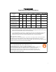
ѻક䇈ᯢк䰘ӊ Supplement to Product Instructions 䚼ӊৡ⿄ (Parts) 䞥ሲ䚼ӊ (Metal Parts) ⬉䏃ഫ (Circuit Modules) ⬉㓚ঞ⬉㓚㒘ӊ (Cables & Cable Assemblies) ล᭭㘮ড়⠽䚼ӊ (Plastic and Polymeric parts) ⬉䏃ᓔ݇ (Circuit Breakers) ƻ˖ 䪙 3E ᳝↦᳝ᆇ⠽䋼ܗ㋴ (Hazardous Substance) ⒈㘨㣃 ∲ 䬝 ݁Ӌ䫀 3%% +J &G &U h ƻ ƻ h ƻ ƻ h ƻ ƻ h ƻ ƻ h ƻ ƻ h ƻ ƻ ƻ ƻ ƻ ƻ ƻ h ƻ ƻ h h ƻ ƻ ⒈Ѡ㣃䝮 3%'( 㸼⼎䆹᳝↦᳝ᆇ⠽䋼䆹䚼ӊ᠔᳝ഛ䋼ᴤ᭭Ёⱘ䞣ഛ SJ/T 11363-2006 ᷛޚ㾘ᅮⱘ䰤䞣㽕∖ҹϟDŽ Indicates that the concentration of the hazardous substance
VCCI Notice This is a class A product based on the standard of the Voluntary Control Council for Interference by Information Technology Equipment (VCCI) V‐3. If this equipment is used in a domestic environment, radio disturbance may arise. When such trouble occurs, the user may be required to take corrective actions. BSMI EMC Statement — Taiwan This is a class A product. In a domestic environment this product may cause radio interference in which case the user may be required to take adequate measures.
Australian Telecom N826 WARNING: Do not install phone line connections during an electrical storm. WARNING: Do not connect phone line until the interface has been configured through local management. The service provider may shut off service if an un‐configured interface is connected to the phone lines. WARNING: The NIM‐BRI‐ST cannot be connected directly to outside lines. An approved channel service unit (CSU) must be used for connection to the ISDN network.
Enterasys Networks, Inc. Firmware License Agreement BEFORE OPENING OR UTILIZING THE ENCLOSED PRODUCT, CAREFULLY READ THIS LICENSE AGREEMENT. This document is an agreement (“Agreement”) between the end user (“You”) and Enterasys Networks, Inc.
If the Program is exported from the United States pursuant to the License Exception TSR under the U.S.
11. ASSIGNMENT. You may not assign, transfer or sublicense this Agreement or any of Your rights or obligations under this Agreement, except that You may assign this Agreement to any person or entity which acquires substantially all of Your stock assets. Enterasys may assign this Agreement in its sole discretion. This Agreement shall be binding upon and inure to the benefit of the parties, their legal representatives, permitted transferees, successors and assigns as permitted by this Agreement.
Contents About This Guide Contents of the Guide .......................................................................................................................................xv Conventions Used in This Guide ......................................................................................................................xv Getting Help ....................................................................................................................................................
PRI Configuration ..................................................................................................................................... 3-8 BRI Configuration ..................................................................................................................................... 3-9 BRI Leased Line ................................................................................................................................. 3-9 BRI Leased Frame Relay ...........................
bU ........................................................................................................................................................... 3-37 cd ........................................................................................................................................................... 3-37 da ........................................................................................................................................................... 3-37 df .................
xiv
About This Guide This guide provides a general overview of the XSR‐3150 hardware and software features and describes how to quickly install and configure the XSR. Refer to the XSR CLI Reference Guide and XSR User’s Guide for information not contained in this document. This guide is written for administrators who want to configure the X‐Pedition Security Router or experienced users who are knowledgeable of basic networking principles.
Electrical Hazard: Warns against an action that could result in personal injury or death due to an electrical hazard. Riesgo Electrico: Advierte contra una acción que pudiera resultar en lesión corporal o la muerte debido a un riesgo eléctrico. Elektrischer Gefahrenhinweis: Installationen sollten nur durch ausgebildetes und qualifiziertes. Personal vorgenommen werden. Warning: Warns against an action that could result in personal injury or death.
Getting Help For additional support related to the XSR, contact Enterasys Networks using one of the following methods: World Wide Web www.enterasys.com/support/ Phone 1-800-872-8440 (toll-free in U.S. and Canada) or 1-978-684-1000 To find the Enterasys Networks Support toll-free number in your country: www.enterasys.com/support/ Internet mail support@enterasys.com To expedite your message, type [xsr] in the subject line. FTP Login Password ftp://ftp.enterasys.
xviii
1 Overview This chapter introduces the key features of the XSR-3150 and briefly describes hardware installation. System Description The XSR is a networking device designed for enterprise regional offices that provides IP routing over GigabitEthernet LAN and T1/E1, Serial (RS232, X.21, V.35, RS422/530, RS449), Dial Services via POTS, ISDN (BRI/PRI) or Frame Relay WAN connections. Virtual Private Network (VPN) support is also provided in Site-to-Site or Remote Access applications.
System Description Figure 1-1 Typical XSR-3150 Topology XSR-3150 XSR XSR Hardware Features The semi-modular XSR, shown in Figure 1-2, comes equipped with the following features: 1-2 Overview • Standard 1U chassis (1-11/16 inches high by 17 inches wide by 21 inches deep) mountable in a standard 19” rack.
System Description Figure 1-2 XSR-3150 SE CU XS R RITY RO -31 UT ER S 50 NIM 1 NIM 2 NIM 1 NIM SY PW S 2 VP N R CO M CO M Lin k 10 00 TX 10 /10 0/1 00 GB IC 0 10 /10 ET H1 ET H2 • 0/1 00 0 ET H3 Two Network Interface Module (NIM) card slots for these NIMs: – 1, 2, or 4 full, fractional and channelized T1/E1 WAN NIM with integral CSU/DSU or Primary Rate Interface (PRI) ports (RJ-48C). – 1-port T3/E3 channelized/unchannelized WAN NIM with BNC ports.
System Description • 14 diagnostic LEDs to display port and system status as well as indicate a Flash upgrade in progress. • Five system fans with failure detection capability and three in-board fans dedicated to power supply cooling.
System Description • Simple Network Time Protocol (SNTP) server • OS fallback IP Routing • Static and multiple routes to the same destination • Redistribution of routes from RIP, OSPF, BGP, connected, or static into RIP, OSPF, and BGP • RIP-1 & RIP-2 • Open Shortest Path First Protocol (OSPF) • OSPF over Generic Routing Encapsulation (GRE): RFC-2784 • Virtual Router Redundancy Protocol (VRRP) • Configurable administrative distance (route preference) per protocol for RIP, OSPF and BGP, and
System Description Security • Stateful inspection firewall engine • FTP, H.
System Description • Periodic Keep-Alive messages to learn of connection problems • Multi-protocol interconnect over Frame Relay - RFC-2427 • RFC-2390 Frame Relay Inverse ARP to discover IP address of remote peer when used in multipoint mode and responds to incoming Inverse ARP requests independent of P2P or MP2P • Multiple logical interfaces over the same physical Frame Relay port: sub-interfaces • Quality of Service: standard FIFO queuing, or IP QoS on DLCIs.
System Description • Bandwidth optimization (BoD) & Dial on Demand (DoD) • Bandwidth Allocation Protocol (BAP) • Security: PAP/CHAP • Call monitoring • Multilink PPP (MLPPP) • Per call activation for NTT switches • Frame Relay over ISDN Quality of Service (QoS) • Traffic classification using IP Precedence and DiffServ Code Point (DSCP) bits, and multiplefield (L3, L4 and other headers) inspection. Match-any and match-all options also define a classmap.
System Description Certificates (embedded/smart cards) – Microsoft only • Encryption • Advanced Encryption Standard (AES), Triple Data Encryption Standard (3DES), Data Encryption Standard (DES) • 3DES/DES acceleration • Data Integrity • MD5 & SHA-1 algorithms • Internet Protocol Security (IPsec) • Encapsulating Security Payload (ESP), Authentication Header (AH) & IPComp • Tunnel & Transport mode • Diffie-Hellman Groups 1 & 2 • Mode Config for IP address assignment • NAT Traversal via UDP encapsulation
System Description Asynchronous Digital Subscriber Line (ADSL) • POTS and ISDN circuit support • ATM Frame UNI (FUNI) data framing format • OAM cells: AIS, RDI, CC, Loopback over F4 and F5 flows • Up to 30 ATM Permanent Virtual Circuits (PVCs) • ATM UBR traffic class • ATM Adaption Layers 0, 5 • PDU encapsulation types: • PPP over ATM (PPPoA) (routed) • IP over ATM (routed) • PPP over Ethernet over ATM (PPPoE) (routed) • Responds to inverse ARP requests • Maintenance of SNMP Interface and
Installation Overview • Switched PPP Multilink connections • Backup using ISDN & MLPPP connections • Dialer interface spoofing • Dialer watch Installation Overview Installing the XSR consists of performing the following general steps. For detailed instructions, refer to Chapters 2 and 3 of this manual. 1 Unpack the XSR from the shipping box. Remove accessories. Items included in the shipping box are shown in Chapter 2 of this manual.
Installation Overview 1-12 Overview
2 Hardware Installation Introduction This chapter provides a checklist to verify your shipment, suggestions for the installation site, and describes how to install the following XSR hardware: • NIM cards • Optional - CompactFlash card • Connecting cables Note: For instructions on installing a balun and grounding shunt/terminal strip on E1 NIM cards only, refer to Appendix A: Specifications on page A-1.
Installing NIM Cards and Rack Mounting • Each XSR AC power supply requires a three-pronged power receptacle capable of delivering the current and voltage specified in Appendix A. An AC outlet on a separately fused circuit is required for each XSR to provide power redundancy, and must be located within 182 centimeters (6 feet) from the site. The power cord used and type of outlet is dependent on the country. In the United States, a power cord with a NEMA 5-15P plug is provided with each XSR.
Installing NIM Cards and Rack Mounting 4. Remove the NIM slot cover, as shown in Figure 2-2, by grasping the handle and pressing it to the side before pulling it out. Figure 2-2 SE XS CU RIT R- YR OU 31 Removing NIM Slot Covers TE RS 50 NIM 1 NIM 5. 2 Carefully attach the NIM card(s) to the connector on the motherboard and secure with four screws, as shown in Figure 2-3.
Installing NIM Cards and Rack Mounting 7. Attach the rack brackets to the chassis with the screws supplied, as shown in Figure 2-4. Figure 2-4 Fastening Rack Brackets SE CU Y RO XS R-3 UTERS 15 0 RIT NIM 1 NIM 2 NIM1 NIM2 SY PW S VP R N CO M Lin k CO M 10 00 10 TX /100 /100 GB IC 0 10 ET H1 /100 ET H2 8. /100 Mount the bracketed XSR to your rack, as shown in Figure 2-5.
Installing a CompactFlash Memory Card Installing a CompactFlash Memory Card An optional CompactFlash (CF) memory card provides additional non-volatile storage capabilities in 8, 16, 32, or 64 Mbyte increments. The CF’s controller interfaces with a host system allowing data to be written to and read from the CF’s flash memory module. The XSR supports Type I and II CompactFlash card types. Refer to Figure 2-6 for a generic illustration of the card. The CF’s memory is large enough to store image files.
Installing a CompactFlash Memory Card Gently insert the CF into the slot, taking care that the CF’s wider grooved edge fits into the wider track of the PCMCIA interface. If the card does not seat easily but stops halfway into the slot, do not force it in - the card was inserted incorrectly. Flip it over and re-insert. Note that the XSR’s CF eject mechanism pops out for easy removal when you install the card.
Connecting Cables Connecting Cables Perform any of the following steps to connect your cabling to optional WAN or LAN NIMs, GigabitEthernet ports, and power supplies: 1. Connect the serial COM cable provided in the packing box to your PC connector, as shown in Figure 2-9. Figure 2-9 CO Connecting Serial COM (Console) Cable Lin M k 10 00 TX 10 /10 0/1 00 GB 0 10 /10 IC ET H1 0/1 00 0 ET H2 ET H3 2.
Connecting Cables Figure 2-11 Connecting High Speed Serial Connector SE CU XS RIT R- YR OU 31 TE 50 RS NIM 1 NIM Figure 2-12 2 Attaching T3/E3 BNC Connectors SE CU RIT YR OU TE RS XS R- 31 50 Tx NIM AL 1 AR M LO S EN AB LE LO F Rx id NIM 2-8 Hardware Installation 2
Connecting Cables Figure 2-13 SE CU XS Connecting ADSL Connector RIT R- YR OU 31 TE 50 RS NIM 1 NIM 2 A CompactFlash card is provided with the XSR ADSL NIM. It is loaded with the Digital Signal Processing (DSP) firmware (adsl.fls) required to communicate with your DSLAM. When inserted into the Compact Flash slot - upon first configuring an ATM interface - the XSR’s ADSL driver will copy adsl.fls into host memory where it will remain available for use on demand.
Connecting Cables 3. Connect the Ethernet port(s) to your LAN connectors with a cable, as shown in Figure 2-15. Figure 2-15 CO M Lin k 10 00 TX Attaching GigabitEthernet Connector 10 /10 0/1 00 0 GB 10 /10 IC 0/1 ET 00 H1 0 ET H2 ET H3 4. Insert the Mini-GBIC module in the GBIC slot then connect the optical cable, as shown in Figure 2-16.
Connecting Cables Attach either the Ethernet or Fiber Ethernet LAN NIM, as shown in Figure 2-17 and Figure 2-18, respectively. Figure 2-17 Attaching Ethernet LAN NIM Connector SE CU RIT YR OU TE RS XS R- 31 50 NIM 1 NIMETHR01 LINK ACT NIM Figure 2-18 RIT YR OU 31 TE 50 RS NIM 1 NIMFIBR01 CU R- Attaching Ethernet Fiber LAN NIM Connector ACT SE XS 2 LINK 5.
Connecting Cables 6. Attach the dual power supply cords to the connectors at the rear of the XSR, as shown in Figure 2-19, and plug in the country-specific power cords to a wall socket. The XSR will power up. Figure 2-19 Connecting Dual Internal Power Supply Cords 10 LI 0~ NE 20 125V 0~ 24 ~1 0V .25 50 ~0 A /60 .65 Hz A 10 LI 0~ NE 20 125V 0~ 24 ~1 0V .25 50 ~0 A /60 .65 Hz A You are now ready to configure the software and initialize the XSR. Continue with “Software Configuration” on page 3-1.
3 Software Configuration This chapter describes how to initialize, quickly set up and verify your configuration for the XSR. Refer to the XSR CLI Reference Guide for a more thorough explanation of commands and parameter options. The chapter also includes sample configuration scripts, detailed XSR rebooting characteristics and Bootrom Monitor mode instructions.
Initializing XSR Software • ETH 10/100/1000 LEDs turn ON and OFF a few times during initialization as the XSR proceeds from bootrom to power up diagnostics to software image, then they remain ON or OFF depending on the LAN type. • ETHERNET Activity LEDs blink when frames pass on the LAN. • COM Activity LED is OFF until the CLI comes up. Then it blinks ON/OFF during console keyboard input or output. • NIM LEDs are OFF until the CLI comes up.
Opening a COM (Console) Session only the first error will be reported, along with a count of the sum of errors incurred. In the case of a single error, only the error line will be reported. Error messages will be logged as well. Because the result of continuing to process a flawed startup-config is not predictable, the nature and position of the syntax error may cause the erroneous configuration of the XSR. • Router ports and protocol stacks are initialized based on startup configuration.
Optional: Configuring Remote Auto Install Note the use of a helper-address to specify a destination address for UDP broadcasts and forward traffic to the DNS and TFTP servers. In the example below, DNS and TFTP servers reside on the same node - 10.10.1.2 (configuration of DNS and TFTP servers are not shown here). In short, the DNS server should map IP addresses 133.133.1.2 and 133.133.1.3 to hostnames.
Optional: Configuring Remote Auto Install + TFTP transfer succeeded in copying the hostname file to the Flash: startup-config file. ****************** REMOTE AUTO INSTALL TERMINATING***************** + The RAI process is complete and is preoceding to system initialization where it will process the new startupconfig file. Configuring RAI for DHCP over LAN The following example configures DHCP server to be used with RAI over Ethernet.
Optional: Configuring Remote Auto Install + Creates a VPDN session group and links it to a virtual template. accept-dialin protocol pppoe virtual-template 1 pppoe limit per-mac 10 + This is an optional command. pppoe limit max-sessions 32000 + This is an optional command. interface GigabitEthernet1/0/0 no ip address negotiation auto ! interface GigabitEthernet1/0/0.10 encapsulation dot1Q 20 pppoe enable pppoe max-sessions 10 + Optional.
Configuring the XSR Name and User Information Phase 3 - ADSL - trying to connect on 0/35 with snap PPPoE + PVC 0/35 is found, SNAP PPPoE encapsulation is applied and authentication tried if required. Phase 3 - ADSL - waiting for IP to connect (54 sec) + The XSR waits one minute for the PPPoE connection to come up. Phase 4 - ADSL - IP is connected on 0/35, prepare to load startup config + The XSR starts downloading the startup-file.
Configuring the LAN Ports Enter the following command to configure the XSR as an SNTP client: XSR(config)#sntp-client server [primary | A.B.C.D.][alternate | A.B.C.D.] Enter the following command to configure the XSR as an SNTP server: XSR(config)#sntp-server enable Remember to save your configuration after all edits. Configuring the LAN Ports 1. Enter interface gigabitethernet <1 | 2 | 3> to acquire Interface mode and select one of the GigabitEthernet ports. 2. Enter ip address
Configuring the WAN Ports This command allows multiple logical WAN interfaces to be created on a single channelized T1/E1/ISDN-PRI port, ranging from 0 - 23 for T1 lines, and 0 - 31 for E1 lines. Also, from 1 - 24 T1 and 1 - 31 E1 timeslots can be set. Channel speed options are 56 (T1) or 64 (E1) kbps. Note: Channel group and timeslot number ranges are different. Be sure to match them correctly and within the range. Also, when adding a second T1 or E1, be sure to begin channel numbering again at 0. 6.
Configuring the WAN Ports 4. Enter encapsulation ppp to select PPP encoding. 5. Enter no shutdown to keep the BRI interface enabled. BRI Leased Frame Relay 1. Enter interface bri 0:<1 | 2>.<1-30> to acquire BRI Interface mode and select the BRI port and channel 1 or 2. 2. Enter encapsulation frame-relay to select Frame Relay encoding. 3. Enter no shutdown to keep the BRI interface enabled. 4.
Configuring the WAN Ports ADSL Configuration ADSL can be configured using three different types of encapsulation: PPPoA, PPPoE, and IPoA. Continue configuration with the ADSL type of your choice. PPPoE The following commands configure a sample PPPoE topology. The first set configures the LAN interface with directed broadcasts prohibited. XSR(config)#interface XSR(config-if)#ip XSR(config-if)#no XSR(config-if)#no FastEthernet 1 address 192.168.1.1 255.255.255.
Firewall Sample Configuration The commands below configure the ATM interface and sub-interface with a negotiated IP address, CHAP username and password, and bans keepalives. XSR(config)#interface ATM 0 XSR(config-if)#no shutdown XSR(config-if)#interface ATM 0.1 XSR(config-if)#no shutdown XSR(config-if)#encapsulation snap pppoa XSR(config-if)#ip address negotiated XSR(config-if)#ip mtu 1492 XSR(config-if
Firewall Sample Configuration Figure 3-1 XSR with Firewall Topology 220.150.2.32/28 XSR Frame Relay Internet S1 206.12.44.16/28 220.150.2.35 SECU RITY ROUT XSR ERS -185 0 POW ER 220.150.2.37 10/10 0BT SYS ACT VPN ETHE RNET PORT 1 10/10 0BT ACT ETHE RNET PORT 2 CONS OLE NIM 1 NIM FE1 2 FE2 220.150.2.17 Internal 220.150.2.16/28 220.150.2.36 DMZ Mail server (SMTP) 220.150.2.18 Web server (HTTP) 220.150.2.
Setting Up RIP Routing XSR(config)#ip firewall filter allowICMP private dmz protocol-id 1 XSR(config)#ip firewall filter allowICMP private ANY_EXTERNAL protocol-id 1 XSR(config)#ip firewall filter allowICMP ANY_EXTERNAL dmz protocol-id 1 Trial load the completed configuration into the firewall engine, and if successful, load the configuration: XSR(config)#ip firewall load trial XSR(config)#ip firewall load Complete LAN and WAN interface configuration: XSR(config)#interface gigabitethernet 1 XSR(config-if
Configure OSPF Routing 10. Enter ip rip receive version <1 | 2> to allow a RIP version of updated transmissions. Accept both RIP V1 and V2 is the default value. 11. Enter router rip to acquire Router configuration mode and enable RIP routing. 12. Enter network (IP address) of the network to be advertised. Repeat the command to configure additional networks. 13. Enter passive-interface type num if you want to prevent RIP transmissions on the interface. 14.
Setting Up an SNMP Community String, Traps and V3 Values 5. Enter media-type V35 to match the correct cabling interface. The default media type for Frame Relay is RS-232. 6. Enter frame-relay traffic-shaping to enable congestion control. 7. Enter map-class frame-relay to designate this map-class and acquire Map-Class mode. 8. Enter frame-relay cir out to set the outgoing CIR (the default is 56000 bps). Refer to the XSR User’s Guide for more details. 9.
Configuring Message Logging and Severity Level 5. Optional . For SNMPv3, enter snmp-server group v3 {auth | nonauth | priv} read write to add a group. Groups offer users authorization choices and read/write privileges. Note: Because only one operator can set the XSR at any time, you must exit Global mode to perform SNMPv3 configuration. Otherwise, the SNMP set request will fail with the “resource unavailable” message. This rule applies to configuration values, not image downloads. 6.
Viewing Your Configuration Viewing Your Configuration 1. Enter show running-config to verify your current configuration. The XSR will display the commands you issued up to this point. Default values are not displayed. Note: All show commands can be entered in privileged EXEC mode - XSR# - or Global configuration mode - XSR(config)#. Connecting Remotely via the Web 1. Enter configure to acquire Configuration mode. 2. Enter ip http server enable to access the XSR over the Web. 3.
Connecting Remotely via the Web Click on Product Version to bring up the Product Version window for a host of hardware, bootrom, and software information as shown in Figure 3-3. Figure 3-3 Web Product Version Window Product Version Copyright 2004 by Enterasys Networks, Inc. Hardware: Processor board ID: 9002854-02 REV0A Serial Number: (not displayed) Processor: IBM PowerPC 405GP Rev.
LAN-PPP Services Sample Configuration LAN-PPP Services Sample Configuration The sample configuration below, see Figure 3-4, creates a PPP, fractional T1 leased line connection from the XSR branch node to the Central Site router and a backup serial dialup link to the Backup Site regional router. Figure 3-4 Hostname: Username: Password: Sample LAN-PPP Services Configuration branch1 mainsite Toronto Hostname: Username: Password: mainsite branch1 Toronto 192.168.1.100/24 XSR-3150 154.168.1.
LAN-PPP Services Sample Configuration XSR(config-controller)#no shutdown + Enables T1 controller XSR(config)#interface serial 1/0:0 + Configures Serial interface 1, port 1 using channel group 0 and acquires Interface mode XSR(config-if)#encapsulation ppp + Enables PPP encapsulation XSR(config-if)#ppp authentication chap + Configures CHAP authentication on the interface XSR(config-if)#ip address 154.68.1.47 255.255.255.
Frame Relay WAN Link with PPP Backup Sample Configuration Frame Relay WAN Link with PPP Backup Sample Configuration The sample configuration below, similar to the preceding configuration except that the cloud supporting the primary line is Frame Relay rather than Public Service Telephone Network, configures one LAN port, the Frame Relay WAN, QoS, OSPF routing, DHCP Relay, IP broadcast forwarding, SNMP with ACL rules, and access lists.
Frame Relay WAN Link with PPP Backup Sample Configuration XSR(config-cmap)#match access-group 133 + Assigns ACL 133 to this class map XSR(config)#policy-map priority-policy + Adds a policy map and acquires Policy Map mode XSR(config-pmap)#class rtp_class + Adds a queue for this policy map and acquires Class sub-mode XSR(config-pmap-c)#priority high 30 3200 + Gives high priority queue a peak 30% of bandwidth and a burst size of 3200 bits per second XSR(config-pm
Frame Relay WAN Link with PPP Backup Sample Configuration XSR(config)#interface serial 1/0.2 multipoint + Configures FR port: Serial card in slot 1, port 0, sub-interface 2 for multipoint links and acquires Interface mode XSR(config-if)#frame-relay class CLASS_SI + Adds another FR map class XSR(config-if)#frame-relay interface-dlci 16 + Adds PVC #16 and acquires DLCI 16 sub-mode XSR(config-if)#class CLASS_DLCI + Assigns the specified map class to DLCI 16 XSR(config-if
Frame Relay WAN Link with PPP Backup Sample Configuration Configure OSPF Routing XSR(config)#router ospf 1 + Enables OSPF with a router ID and acquires Router mode XSR(config-router)#network 192.168.1.0 0.0.0.255 area 0.0.0.10 + Configures the area ID for the specified network XSR(config-router)#network 154.68.1.0 0.0.0.255 area 0.0.0.0 + Configures another area ID for the specified network Configure More Access Lists The following ACLs deny any packets to or from network 192.168.1.
Frame Relay WAN Link with PPP Backup Sample Configuration XSR(config-if)#encapsulation ppp + Enables PPP encapsulation XSR(config-if)#ip address 192.31.27.84 255.255.255.
VPN Site-to-Site Sample Configuration VPN Site-to-Site Sample Configuration The following VPN topology, shown in Figure 3-5, configures a central site XSR to connect over IPSec tunnels with a remote ANG-1105 and two XSRs. Figure 3-5 VPN Site-to-Site Topology 112.16.72.2 Central Site 112.16.244.9 ANG-1105 112.16.1.221 Branch Sites XSR SECU RITY XSR ROUT ERS -185 0 112.16.76.
VPN Site-to-Site Sample Configuration XSR(config)#access-list XSR(config)#access-list XSR(config)#access-list XSR(config)#access-list XSR(config)#access-list 101 101 190 191 192 permit udp ah any any deny ip any any permit ip any 112.16.72.0 0.0.0.255 permit ip any 112.16.76.0 0.0.0.255 permit ip any 112.16.80.0 0.0.0.
VPN Site-to-Site Sample Configuration XSR(config)#crypto map acme 91 XSR(config-crypto-m)#set transform-set esp-3des-sha XSR(config-crypto-m)#match address 191 XSR(config-crypto-m)#set peer 112.16.244.7 XSR(config)#crypto map acme 90 XSR(config-crypto-m)#set transform-set esp-3des-sha XSR(config-crypto-m)#match address 190 XSR(config-crypto-m)#set peer 112.16.244.
VPN Sample Configuration with Network Extension Mode Configuring Authentication (AAA) Configure an AAA user and DEFAULT AAA group for remote users. When an ANG tunnels into the XSR, it will be assigned dynamically to the IP pool AUTH. Be aware that groups must be created before users can be added to them. Remember to create the same users and passwords on the ANG. The IP address assigned to the AAA user is the remote gatewayIP address. XSR(config)#ip local pool AUTH 192.168.2.0 255.255.255.
VPN Sample Configuration with Network Extension Mode Generate the master key. Refer to the following sample key: XSR(config)#crypto key master generate New key is 2173 4521 3764 2ff5 163b 4bdf fe92 dbc1 1232 ffe0 f8d9 3649 Apply the following ACLs to the public interface of the XSR before creating the VPN configuration. These ACLs are applied only to an XSR configured to terminate Network Extension Mode (NEM) tunnels initiated from ANG-1100s.
VPN Sample Configuration with Network Extension Mode Create user(s), specify an IP from virtual subnet, and assign a password: XSR(config)#aaa user XSR(config)#password XSR(config)#aaa user XSR(config)#password nem-test welcome jeffb welcome Check to make sure the transforms and proposals were created properly: XSR#show crypto ipsec transform-set Name PFS -----*ez-esp-3des-sha-pfs Modp768 *ez-esp-3des-sha-no-pfs Disabled *ez-esp-3des-md5-pfs Modp768 *ez-esp-3des-md5-no-pfs Disabled *ez-esp-aes-sha-pfs Mo
XSR Rebooting Characteristics Create the multi-point VPN virtual port required to terminate many clients: XSR(config)#interface vpn1 multi-point XSR(config)#description “VPN Virtual Interface Int0” XSR(config)#ip address 10.10.10.1/24 XSR(config)#ip rip send version 2 XSR(config)#ip rip receive version 2 XSR(config)#ip multicast-redirect tunnel-endpoint Enable RIP routing on all networks except the public interface: XSR(config)#router rip XSR(config)#network 172.16.10.0 XSR(config)#network 10.0.0.
XSR Rebooting Characteristics Testing S/W Integrity << PASSED >> Loading Router S/W to address 0x80020000 Verifying uncompressed chksum ... Starting from 0x80020000... Attaching shared memory objects at 0xa0000600... done Attaching interface lo0...done Verifying flash:xsr3000.fls file ...
Bootrom Monitor Mode Commands Reload Command from the CLI You can reboot the XSR firmware by issuing the command reload . You are then prompted to confirm the command. Once the firmware is reloaded, the configuration is loaded from the startup-config file. Bootrom Monitor Commands bc and bw Using Bootrom Monitor mode, you can activate warm or cold reboots by entering bw or bc, respectively. Refer to “Bootrom Monitor Mode Commands” on page 3-35 for more data.
Bootrom Monitor Mode Commands All the commands in each group can be listed by entering the command group letter.
Bootrom Monitor Mode Commands bootFirst size=28992 sum=0xc2e5 compressed_size=28992 entry=0x80020000 bootrom size=842656 sum=0xfa65 compressed_size=347728 entry=0x81e00000 OK Proceed with erasing current Bootrom in flash and replace with btXSR3000_1_2.fls? (y/n) y First copy of Bootrom ...
Bootrom Monitor Mode Commands df This command shows free disk space. Sample output is shown as follows: XSR-3150:df Free space on flash: is 3383296 bytes (0x33a000). del This command removes a file from flash: or cflash: memory. dir This command lists the contents of the current directory in long format. The command displays the following sample output: XSR-3150: dir Listing Directory flash:: -rwxrwxrwx 1 0 0 -rwxrwxrwx 1 0 0 -rwxrwxrwx 1 0 0 -rwxrwxrwx 1 0 0 4678118 2228 1153 0 May 5 23:06 xsr3000.
Bootrom Monitor Mode Commands Set working directory to flash: Using default Bootrom password. The system is not secure!!! Use “bp” to change password ffc This command formats the CompactFlash card. ng This command retrieves a file over the network using a remote IP address/file path. np This command modifies network parameters. You are prompted to enter data by the following script. While most of the options are self-explanatory, three require further description.
Bootrom Monitor Mode Commands remove This command removes a file using the syntax remove rename This command renames a file using the syntax rename sb This command displays boot values. Sample output is shown as follows: XSR-3150: sb Current boot file is xsr3000.fls Boot selector default is flashrom, compactFlash, network Available Network boot devices: sbe0 sf This command displays a fault report. Sample output is shown as follows.
Bootrom Monitor Mode Commands ...... si This command displays XSR 3000 Series inventory with this sample output: XSR-3150: si Hardware: Motherboard Information: XSR-3150 ID: 9002914-04 REV0A CPLD Rev 3 Serial Number: 2914024201123206 Processor: Broadcom BCM1250 Rev 2 at 600MHz PowerSupply1, PowerSupply2 Fans 1 2 3 4 5 7 8 10 CPU Temperature Max: 80C Current: 35C Router Temperature Max: 60C Current: 23C RAM: 512MB without interleave Memory Bus at 120MHz, CASL at 2.
Bootrom Monitor Mode Commands sv This command shows the bootrom version with sample output below: XSR-3150: sv X-Pedition Security Router Bootrom Copyright 2003 Enterasys Networks Inc. HW Version: 9002914-04 REV0A Serial Number: 3646031700233215 CPU: Broadcom BCM1250 Rev 2 VxWorks version: VxWorks5.4.2 Bootrom version: 1.
A Specifications System Specifications This appendix details XSR data about hardware functionality including: • Processor, system memory, chassis, power supply, interfaces • Required cabling, CompactFlash and other accessories • Pinout assignments for WAN and LAN interfaces • LED behavior Refer to tables throughout this appendix for specific information.
Cable, CompactFlash and Accessory Specifications Table A-1 Category XSR Hardware Specifications (continued) Parameters Power Consumption Typical values: Motherboard: 75 watts (maximum) Serial NIM card: 4 watts T1/E1/ISDN-PRI NIM card: 3 watts ISDN BRI-S/T NIM card: 1 watt Internal Power Supplies (2) Type Dual universal (110/220 VAC) load-sharing, redundant units Input AC Voltage & Frequency 100-125 Vac, 1.7A 200-240 Vac, 0.
Cable, CompactFlash and Accessory Specifications Table A-2 XSR Cabling/Accessory Guide (continued) Part Description Connector Part # Function 1000Base-SX Mini-GBIC with connector 1000Base-LX Mini-GBIC with connector 1000Base-SX Mini-GBIC with connector Short-haul LC Long-haul LC Short-haul MTRJ MGBIC-LC01 MGBIC-LC09 MGBIC-MT01 Ethernet link to 1000BaseT line Ethernet link to 1000BaseT line Ethernet link to 1000BaseT line 2-port synch/asynch card 4-port synch/asynch card 68-pin, male SCSI III NI
Cable, CompactFlash and Accessory Specifications COM (Console) Port The XSR comes equipped with a COM serial port useful for initial configuration and management. Using a serial (null modem) cable, you can attach the router’s DB-9 COM port to a data terminal port and directly configure the XSR over the asynchronous connection. Then, open a communications or Telnet session to communicate with the router.
Cable, CompactFlash and Accessory Specifications GigabitEthernet Ports The XSR comes equipped with three GigabitEthernet (LAN) ports that support full-duplex 10, 100, or 1000 Mbps transmission. The ports conform to IEEE 802.3 standards with 8-pin modular RJ-45 connectors.
Cable, CompactFlash and Accessory Specifications Copper/Fiber-optic Ethernet NIMs The single-port Copper or Fiber-optic Ethernet NIMs, shown in Figure A-3 and Figure A-4, provide interfaces for half and full-duplex 10/100Base-T or fiber-optic 100Base-F transmission over LAN or WAN networks, respectively. The Copper Ethernet NIM incorporates a standard 8pin modular RJ-45 connector and the Fiber-optic Ethernet NIM has an MT-RJ multi-mode interface. Both NIMs conform to IEEE 802.3 and PCI 2.2 standards.
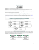
Cable, CompactFlash and Accessory Specifications 2/4-Port Serial NIM Card Port The High Speed Serial NIM card, as shown in Figure A-6, provides a WAN interface supporting a serial link to four different types of DTEs: DB-15, 25, 37, and V.35. This interface supports dual and quad traffic up to 8 Mbps. Figure A-6 High Speed Serial NIM Port 68-pin Serial Pin 1 Pin 68 Refer to Figure A-7 through Figure A-11 for pinout assignments. Figure A-7 J1 3 11 5 10 4 7 6 8 15 16 9 14 X.21 DTE Pin Assignments X.
Cable, CompactFlash and Accessory Specifications Figure A-8 J1 1 2 3 11 5 10 4 7 EIA-232/530 DTE Pin Assignments J2 DSR0+ 6 DSR0- 22 RxD0+ 3 RxD0- 16 TxD0+ 2 TxD0- 14 RTS0+ 4 RTS0- 19 DTR0+ 20 DTR06 8 12 13 15 16 9 14 CTS0TxC0+ 36 37 45 39 44 38 41 42 46 47 49 50 43 48 7 Signal GND 1 J3 DSR1+ DSR1RxD1+ RxD1TxD1+ TxD1RTS1+ RTS1DTR1+ CTS1TxC1RxC1+ 27 21 A-8 52 3 53 16 61 2 55 14 60 4 54 19 57 56 13 58 15 62 12 63 7 Signal GND 65 66 59 64 Shield GND 1 J4
Cable, CompactFlash and Accessory Specifications Figure A-9 J1 1 2 3 11 5 10 4 7 EIA-449 DTE Pin Assignments J2 ON0+ 11 ON0- 29 RD0+ 6 RD0- 24 SD0+ 4 SD0- 22 RS0+ 7 RS0TR0+ 25 12 TR06 8 12 13 15 16 9 14 CS0ST0+ ST0RT0+ 36 37 45 39 44 38 41 42 46 47 49 50 43 48 18 26 11 ON1- 29 RD1SD1+ SD1RS1+ RS1TR1+ 20 31 32 No tes: 1 25- Ind icates Twiste d Pair . 30 is braid on braid ed cable 2. Shield GND 3. Shield GND is drain wire o n foil shield cab 4.
Cable, CompactFlash and Accessory Specifications Figure A-10 J1 1 2 3 11 5 10 4 7 PORT 3 (EIA-232/530) 6 8 12 13 15 16 9 14 35 37 45 39 44 38 40 46 47 49 50 43 48 Combined V.35/EIA-232/530 DTE Pin Assignments J2 DSR3+ DSR3RxD3+ RxD3TxD3+ TxD3RTS3+ RTS3DTR3+ DTR3CTS3+ CTS3TxC3+ TxC3RxC3+ RxC3Signal GND Signal GND 6 22 3 16 2 14 4 19 20 23 5 13 15 12 17 9 7 Shield GND PORT 2 (V.35) E R T P S C H D Y AA V X B Shield GND J1: 68-pin male SCSI III-type connector J3, J5: V.35-type male connector J2.
Cable, CompactFlash and Accessory Specifications Figure A-11 J1 1 3 11 5 10 4 6 12 13 15 16 9 14 V.
Cable, CompactFlash and Accessory Specifications T1/E1/ISDN PRI NIM Card Ports The T1/E1/ISDN PRI NIM, as shown in Figure A-12, comes equipped with either 1, 2 or 4 Ethernet (WAN) ports that support fractional T1/E1 transmission in full-channel, fractional or unchannelized format with 8-pin modular RJ-48C connectors and include a built-in DSU/CSU. Cables required for these ports must be 100-ohm, straight-through, twisted-pair for T1 lines and a 120-ohm version for E1 lines.
Cable, CompactFlash and Accessory Specifications Balun for E1 or PRI NIM Cards Some overseas electrical systems require that you use a balun and grounding shunt when utilizing an E1 or PRI NIM card on the XSR. A balun is an adapter employed to connect a 75-ohm coaxial cable pair (2 BNC connectors) to a 120-ohm twisted pair cable (RJ-48C connector). The balun and its connectors are shown in Figure A-14. The grounding shunt is also required to insulate (ground) unused pins of the RJ-48C connector.
Cable, CompactFlash and Accessory Specifications Grounding Shunt for E1 NIM Cards If you connect a balun to a 75-ohm line, you will also need to attach a grounding shunt (or terminal strip) to any NIM pins whose RJ-48C connectors utilize the balun. The XSR requires that you use a shunt (shown in Figure A-15), or terminal strip to ground pins 3 and 6 of the RJ-48C interface, which are not needed to complete the connection.
Cable, CompactFlash and Accessory Specifications T3/E3 NIM Card The T3/E3 full and sub-rate NIM, as shown in Figure A-17, is equipped with 1 Ethernet (WAN) port that supports fractional T3/E3 transmission in un-channelized or clear channel mode with BNC connectors. User data are encapsulated in HDLC packets before being sent to the line. Figure A-17 Tx 1-Port T3/E3 NIM Card ALARM LOS Rx ENABLE LOF id Cables required for this NIM must be 75-ohm, DS3 Type 734 or 735 coaxial.
Cable, CompactFlash and Accessory Specifications 1/2-Port BRI-S/T ISDB NIM Card Ports The XSR provides a serial NIM card for 1 or 2 WAN interfaces over an ISDN-S/T BRI line, as shown in Figure A-18. The Port 0 and 1 LEDs shine when the lines are active and ready to receive traffic. See Figure A-19 for pinout assignments.
Cable, CompactFlash and Accessory Specifications Installing Shunt/Terminal Strip To install the shunt or terminal strip, attach two dual-pin units vertically to P1 and P2 four-pin jumpers corresponding to the RJ-45 port using a balun, as shown in Figure A-20. Any other RJ-45 ports on the NIM card connected to 120-ohm lines do not require shunts.
Cable, CompactFlash and Accessory Specifications 1/2-Port BRI-U NIM Card Ports The XSR provides a serial NIM card for 1 or 2 WAN interfaces over an ISDN BRI-U line, as shown in Figure A-21. Port 0 and 1 LEDs shine when the lines are active and ready to receive traffic. Figure A-21 ISDN BRI-U NIM Card (RJ-49C ports shown) Port 0 Activation LED Port 1 Activation LED Refer to Figure A-22 for pinout assignments.
Cable, CompactFlash and Accessory Specifications 1-Port ADSL NIM Card Port The XSR’s Asymmetric Digital Subscriber Line (ADSL) NIM card, as shown in Figure A-23, provides 1 WAN port on an ADSL over POTS (Annex A/C) or ISDN (Annex B) line with a 6-pin RJ-11 connector. The ADSL NIM supports both G.dmt and G.lite standards. ADSL NIMs are shipped with a CompactFlash card containing DSP firmware. This driver software copies the Flash file into host memory where it provides on-demand use by the DSP.
Cable, CompactFlash and Accessory Specifications T1/E1 Drop & Insert (D&I) NIM The XSR’s 2-port T1/E1 D&I NIM card, as shown in Figure A-25, is designed as an intermediary between the Central Office T1/E1 line and a PBX. It de-couples Channel Associated Signaling (CAS) and Voice DS0 timeslots and redirects them to a PBX, and conversely, reintegrates Voice DS0 timeslots from the PBX with the T1/E1 data stream. Both ports are functionally equivalent.
Cable, CompactFlash and Accessory Specifications CompactFlash Memory Card The optional plug-in CompactFlash (CF) memory card, shown in Figure A-27, comprises a single chip controller and flash memory modules in a matchbook-sized package with a 50-pin, PCMCIA connector consisting of two rows of 25 female contacts each. The PCMCIA male interface supports both Type I and Type II CF cards. Note that the CF release mechanism pops out when you install the card.
Cable, CompactFlash and Accessory Specifications Table A-3 LED State Function VPN ON VPN tunnel is up OFF No VPN tunnel connected Blinking Port is transmitting or receiving data OFF Port is idle Amber only ON 10Base-T link is auto-detected Green only ON 100Base-T link is auto-detected Both ON 1000Base-T link is auto-detected Blinking Port is transmitting or receiving data OFF Link is down Both OFF Port is configured as copper Link LED ON Fiber link up TX LED Blinking Activity on
Index B Balun description A-13 Balun adapter A-3 BRI S/T card part numbers A-3 BRI S/Tpin assignments A-16 BRI U card part numbers A-3 BRI-U pin assignments A-18, A-19, A-20 Broadcom 1250 processor 1-2 C cable/accessory guide A-2 cabling part numbers A-2 Canadian notices iii channelized card specifications A-3 chassis dimensions 1-2 specifications A-1 COM port configuration A-4 port pinouts A-4 serial interface 1-3 session login A-4 session properties 3-3, A-4 session setup 3-3 CompactFlash installation A-
features 1-1 GigabitEthernet port pinouts A-5 hardware features 1-2 hardware specifications A-1 how to attach the Ethernet serial cable 2-10 how to attach the internal power supply cord 2-12 how to attach the serial Console cable 2-7 how to attach the WAN cables 2-7 how to configure Frame Relay 3-15 how to configure IP routing 3-14 how to configure the COM port A-4 how to enable Web access 3-18 how to install a CompactFlash card 2-5 how to install NIM cards 2-2 how to install the hardware 2-1 how to rack mo