
- Enterasys Router Getting Started Guide

Cable, CompactFlash and Accessory Specifications
XSR Getting Started Guide A-21
CompactFlash Memory Card
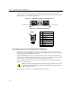
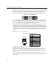
The optional plug-in CompactFlash (CF) memory card, shown in Figure A-27, comprises a single
chip controller and flash memory modules in a matchbook-sized package with a 50-pin, PCMCIA
connector consisting of two rows of 25 female contacts each.
The PCMCIA male interface supports both Type I and Type II CF cards. Note that the CF release
mechanism pops out when you install the card. For installation instructions, refer to the Hardware
Installation chapter.
Figure A-27 CompactFlash Memory Card
LED Behavior
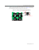
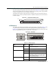
The 14 LEDs on the XSR front panel display system and port status as described in Table A-3. The
six system LEDs are illustrated to the left and the eight GigabitEthernet LEDs to the right in
Figure A-28. Note that Link and TX (transmit) green LEDs are provided for the GBIC (optical) port
while each GigabitEthernet port has one green and one amber LED.
Figure A-28 XSR LEDs
Pin 50
Pin 1
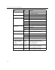
Table A-3 LED Description
LED State Function
NIM 1, NIM 2 ON T1/E1, ISDN or HSSI card is present and power-
up diagnostics test passed
OFF NIM slot empty or power-up diagnostics test failed
SYS(tem Status) ON XSR is operational
OFF Faulty hardware or Bootprom
Blinking Flash update is in progress (software image
downloading), warning you not to power down the
XSR. Powering down now can leave the branch
router without valid software.
PWR ON XSR is powered up and Bootrom initialized
OFF XSR is powered down
COM
PWR
SYS
NIM1 NIM2
VPN
1000
GBIC
Link
TX
ETH3ETH2ETH1
10/100/1000
10/100/1000