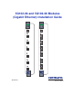
5G102-06 and 5G106-06 Modules (Gigabit Ethernet) Installation Guide Gb ENET 5G102-06 Gb ENET 5G106-06 RESET RESET COM COM CPU 1 2 3 CPU 1 2 3 4 4 5 5 6 6 9033587-01
ELECTRICAL HAZARD: Only qualified personnel should perform installation procedures. NOTICE Enterasys Networks and its licensors reserve the right to make changes in specifications and other information contained in this document without prior notice. The reader should in all cases consult Enterasys Networks to determine whether any such changes have been made. The hardware, firmware, or software described in this manual is subject to change without notice.
FCC NOTICE This device complies with Part 15 of the FCC rules. Operation is subject to the following two conditions: (1) this device may not cause harmful interference, and (2) this device must accept any interference received, including interference that may cause undesired operation. NOTE: This equipment has been tested and found to comply with the limits for a Class A digital device, pursuant to Part 15 of the FCC rules.
ENTERASYS NETWORKS, INC. PROGRAM LICENSE AGREEMENT BEFORE OPENING OR UTILIZING THE ENCLOSED PRODUCT, CAREFULLY READ THIS LICENSE AGREEMENT. This document is an agreement (“Agreement”) between You, the end user, and Enterasys Networks, Inc. (“Enterasys”) that sets forth your rights and obligations with respect to the Enterasys software program (“Program”) in the package. The Program may be contained in firmware, chips or other media.
5. UNITED STATES GOVERNMENT RESTRICTED RIGHTS. The enclosed Product (i) was developed solely at private expense; (ii) contains “restricted computer software” submitted with restricted rights in accordance with section 52.227-19 (a) through (d) of the Commercial Computer Software-Restricted Rights Clause and its successors, and (iii) in all respects is proprietary data belonging to Enterasys and/or its suppliers.
DECLARATION OF CONFORMITY Application of Council Directive(s): 89/336/EEC 73/23/EEC Manufacturer’s Name: Manufacturer’s Address: European Representative Name: European Representative Address: Conformance to Directive(s)/Product Standards: Equipment Type/Environment: Enterasys Networks, Inc. 35 Industrial Way PO Box 5005 Rochester, NH 03867 Mr. Jim Sims Enterasys Networks Ltd.
Contents Figures ............................................................................................................................................ x Tables..............................................................................................................................................xi ABOUT THIS GUIDE Using This Guide........................................................................................................... xiii Structure of This Guide ..............................
3 INSTALLATION 3.1 3.2 3.3 3.4 3.5 3.6 3.7 4 TROUBLESHOOTING 4.1 4.2 4.3 A Using LANVIEW.............................................................................................. 4-1 Troubleshooting Checklist............................................................................... 4-4 Using the RESET Button................................................................................. 4-6 SPECIFICATIONS A.1 A.2 A.3 B Unpacking the Module ................................................
C GPIM SPECIFICATIONS C.1 C.2 C.3 Gigabit Ethernet Specifications ...................................................................... C-1 C.1.1 GPIM-01 Specifications (1000Base-SX)........................................ C-1 C.1.2 GPIM-08 Specifications ................................................................. C-2 C.1.3 GPIM-09 Specifications (1000Base-LX) ........................................ C-3 Physical and Environmental Specifications....................................................
Figures Figure 1-1 3-1 3-2 3-3 3-4 3-5 3-6 3-7 3-8 3-9 3-10 3-11 3-12 3-13 4-1 4-2 B-1 x Page 5G102-06 and 5G106-06 Modules ................................................................................. 1-2 Different Physical Style of GPIMs ................................................................................... 3-3 GPIM Connectors ........................................................................................................... 3-4 Installing a Side Clip GPIM into the Module.......
Tables Table 1-1 3-1 4-1 4-2 A-1 A-2 C-1 C-2 C-3 C-4 C-5 C-6 3-7 Page GPIM Options ............................................................................................................... 1-4 Contents of Module Carton...........................................................................................3-2 LANVIEW LEDs............................................................................................................ 4-2 Troubleshooting Checklist .........................................
About This Guide Welcome to the 5G102-06 and 5G106-06 Gigabit Ethernet Installation Guide. This guide describes the Gigabit Ethernet modules and provides information concerning network requirements, installation, and troubleshooting. For information about how to use Local Management to configure and manage the modules, refer to the MATRIX E5 Series Modules Local Management User’s Guide.
Related Documents Chapter 2, Network Requirements, outlines the network requirements that must be met before installing the module. Chapter 3, Installation, provides instructions on how to install the module, and connect segments to the module. Chapter 4, Troubleshooting, describes the function of the LANVIEW LEDs, which can help to quickly diagnose network/operational problems.
Document Conventions DOCUMENT CONVENTIONS This guide uses the following conventions: NOTE: Calls the reader’s attention to any item of information that may be of special importance. TIP: Conveys helpful hints concerning procedures or actions. CAUTION: Contains information essential to avoid damage to the equipment. ELECTRICAL HAZARD: Warns against an action that could result in personal injury or death due to an electrical hazard.
Getting Help GETTING HELP For additional support related to this product or document, contact Enterasys Networks using one of the following methods: World Wide Web Phone Internet mail FTP Login Password http://www.enterasys.com/ (603) 332-9400 support@enterasys.com ftp://ftp.enterasys.com anonymous your email address To send comments or suggestions concerning this document, contact the Technical Writing Department via the following email address: TechWriting@enterasys.
1 Introduction This chapter introduces the 5G102-06 and 5G106-06 Gigabit Ethernet modules. Unless otherwise noted, the information in this document applies to both modules. Important Notice Depending on the firmware version used in the module, some features described in this document may not be supported. Refer to the Release Notes shipped with the module to determine which features are supported.
Figure 1-1 5G102-06 and 5G106-06 Modules Gb ENET Gb ENET 5G106-06 5G102-06 RESET Button RESET COM Port System LED COM CPU RESET Button RESET COM Port System LED COM CPU Receive (RX) LED Transmit (TX) LED Receive (RX) LED Transmit (TX) LED 1 2 1 Two Gigabit Ethernet Ports for Optional 1000BASE-SX or 1000BASE-LX GPIMs 2 3 3 Six Gigabit Ethernet Ports (1000BASE-T 4 4 Six Fixed Gigabit Ethernet Ports (1000BASE-SX) 5 5 6 6 1-2 Introduction A B 35874_01
Connectivity 5G102-06 and 5G106-06 The module ports can be configured to control traffic in several ways, including prioritizing traffic flow according to the port receiving a tag or the frame tag. The modules can also be configured to establish 802.1Q Virtual Local Area Networks (VLANs) and control the flow of frames associated with each VLAN according to port or VLAN tag included in the frame. Detailed information about VLANs is provided in the MATRIX E5 Series Modules Local Management User’s Guide.
Options The 5G106-06 supports the 1000Base-SX and 1000Base-LX specifications using fiber GPIMs. 1000Base-SX is supported with the GPIM-01 providing one SC fiber optic connector for 50 or 62.5 micron multimode fiber optic cable. 1000Base-LX is supported with the GPIM-09 providing one SC fiber optic connector for 50 or 62.5 micron multimode fiber optic cable, or 10 micron single mode fiber optic cable. The GPIM-08 meets or exceeds the 1000BASE-LX requirements using 10 micron single mode fiber optic cable.
Port/VLAN Redirect Functions 1.4 PORT/VLAN REDIRECT FUNCTIONS The port redirect function, also referred to as “Port Mirroring,” is a troubleshooting tool used to map traffic from a single source port to a single destination port within the module. This feature allows frames, including those with errors, to be copied and sent to an analyzer or RMON probe. The analyzer or RMON probe will see the data as if it were directly connected to the LAN segment of the source port.
Switching Options 1.8 SWITCHING OPTIONS The module provides 802.1Q switching between all of the front panel interfaces. In the 802.1Q mode (the default mode of operation), the module functions as an 802.1D switch until VLANs are configured. Up to 1024 VLANs can be configured. IEEE 802.1Q switching allows migration to Virtual Network technologies without requiring the replacement of existing equipment. 1.9 STANDARDS COMPATIBILITY The modules are fully compliant with the IEEE 802.3ab, 802.3x, 802.
2 Network Requirements Before installing the module, review the requirements and specifications referred to in this chapter concerning the following: • Port Trunking (Section 2.1) • 1000BASE-T (Section 2.2) • 1000BASE-SX (Section 2.3) • 1000BASE-SX/LX for GPIMs (Section 2.4) The network installation must meet the requirements to ensure satisfactory performance of this equipment. Failure to do so will produce poor network performance.
1000BASE-SX Network (Fixed Front Panel Ports) 2.3 1000BASE-SX NETWORK (FIXED FRONT PANEL PORTS) The fixed front panel ports of the 5G106-06 module provide a Gigabit Ethernet connection that supports fiber connections operating at 1000 Mbps (1 Gbps) for 1000BASE-SX compliancy. The device at the other end of the fiber connection must meet IEEE 802.3z Gigabit Ethernet requirements for the devices to operate at Gigabit speed.
3 Installation ELECTRICAL HAZARD: Only qualified personnel should install the module. NOTE: Read the Release Notes shipped with the module to check for any exceptions to the supported features and operation documented in this guide. This chapter provides the instructions to install the 5G102-06 and 5G106-06 modules. A Phillips screwdriver is required to install options into the module. Follow the order of the sections listed below to correctly install the module. • Unpacking the Module (Section 3.
Unpacking the Module 3.1 UNPACKING THE MODULE Unpack the module as follows: 1. Open the box and remove the packing material protecting the module. 2. Verify the contents of the carton as listed in Table 3-1. Table 3-1 Contents of Module Carton Item Quantity 5G102-06 or 5G106-06 1 Antistatic Wrist Strap 1 Manual Accessory Kit 1 3. Remove the tape seal on the non-conductive bag to remove the module. 4. Perform a visual inspection of the module for any signs of physical damage.
Installing Options into the 5G106-06 CAUTION: The GPIM and the module are sensitive to static discharges. Use an antistatic wrist strap and observe all static precautions during this procedure. Failure to do so could result in damage to the GPIM or module. Always leave the GPIM in the antistatic bag in which it was shipped or an equivalent antistatic container until ready to install it.
Installing Options into the 5G106-06 3.2.1.1 Installing the Side Clip GPIM The GPIMs are installed into the module as follows: 1. Attach the antistatic strap (refer to the instructions in the antistatic wrist strap package) before removing the GPIM from the antistatic packaging. 2. Remove the GPIM from the packaging. 3. Hold the GPIM with the network connection port facing away from the module.
Installing Options into the 5G106-06 2 1 Figure 3-3 Installing a Side Clip GPIM into the Module Hinge Side of Door Top of GPIM X X T Network Port R Locking Tab (hidden from view) 20-pin Connector (insertion end) Locking Tab 2549_05 3.2.1.2 Removing the Side Clip GPIM CAUTION: Do NOT remove a GPIM from a slot without unlocking the tabs. This can damage the GPIM. The GPIM and the module are sensitive to static discharges.
Installing Options into the 5G106-06 3.2.2 Locking Bar GPIMs This section describes how to install and remove GPIMs that are equipped with a metal locking bar. Refer to Appendix C for cable specifications for the GPIMs. CAUTION: This section applies only to GPIMs equipped with a metal locking bar. Damage can result to the GPIM and module if the directions in this manual are not followed carefully. The GPIM and the module are sensitive to static discharges.
Installing Options into the 5G106-06 7. The alignment slots on the GPIM must line up with the alignment guides inside the GPIM slot. The top of the GPIM must be next to the hinge side of the GPIM slot door of the module, as shown in Figure 3-5. 8. Gently insert the GPIM (20-pin connector side) into the GPIM slot opening of the module. See Figure 3-5. The door folds in and the slides engage the slots on the sides of the GPIM. If the GPIM does not go in easily, do not force it into the slot.
Installing the Module into the 5C105 Chassis 3.2.2.2 Removing the Locking Bar GPIM CAUTION: Do NOT remove a GPIM from a slot without unlocking the metal locking bar. This can damage the GPIM. The GPIM and the module are sensitive to static discharges. Use an antistatic wrist strap and observe all static precautions during this procedure. Failure to do so could result in damage to the GPIM or module. Always leave the GPIM in the antistatic bag or an equivalent antistatic container when not installed.
Installing the Module into the 5C105 Chassis To install a module, refer to Figure 3-6 and proceed as follows: NOTE: Although the 5G106-06 is shown in Figure 3-6, this procedure applies to both the 5G102-06 or 5G106-06 modules. 1. Remove the blank panel covering the slot in which the module will be installed. All other slots must remain covered to ensure proper airflow and cooling. (Save the blank plate in the event you need to remove the module.) 2. Carefully remove the module from the shipping box.
Installing the Module into the 5C105 Chassis Figure 3-6 Installing a Module into the 5C105 MATRIX E5 Chassis Backplane Slot Number Connector Plastic Locking Tab SERIES 1 2 3 4 5 Gb ENET 5G106-06 PS1 E5 PS2 RESET COM CPU 1 5C105-X 5C105-X 2 3 4 5 6 Metal Back-Panel Circuit Card Card Guides Plastic Locking Tab 35871_02 3-10 Installation
Connecting Cables to the Network 3.4 CONNECTING CABLES TO THE NETWORK To connect cables to the 5G102-06, proceed to Section 3.5, or to Section 3.6 for connections to the 5G106-06. 3.5 CONNECTING THE 5G102-06 TO THE NETWORK This section describes how to connect unshielded twisted pair (UTP) segments from the network or other devices to the 5G102-06 (Section 3.5.1).
Connecting the 5G102-06 to the Network Figure 3-7 Connecting a Twisted Pair Segment to the 5G102-06 Gb ENET 5G102-06 RESET COM CPU Receive LED Transmit LED 1 RJ45 Connector 2 35871_06 3. Verify that a link exists by checking that the port RX (Receive) LED is ON (flashing amber, blinking green, or solid green). If the RX LED is OFF and the TX (Transmit) LED is not blinking amber, perform the following steps until it is on: a.
Connecting the 5G102-06 to the Network Figure 3-8 Crossover Cable RJ45 Pinouts TO RJ45 Switch Port TO Other Device Port RX+ 1 1 RX+ NOTE: RX RX+/RX and TX+/TX must share a common color pair. TX+ 2 2 RX 3 3 TX+ TX 6 6 TX RJ45 to RJ45 3387_04 Figure 3-9 Straight-Through Cable RJ45 Pinouts TO RJ45 Switch Port NOTE: RX+/RX and TX+/TX must share a common color pair.
Connecting the 5G106-06 to the Network 3.6 CONNECTING THE 5G106-06 TO THE NETWORK The following sections describe how to make the fiber optic cable connections. 3.6.1 SC Fiber Connections to the Network The fixed front panel ports 3 through 6 have an SC style connector used to connect to the Gigabit Ethernet network. The GPIM-01, GPIM-08, and the GPIM-09 also have an SC style connector used to connect to the Gigabit Ethernet network.
Connecting the 5G106-06 to the Network Different size and wavelength fiber optic cable is used for different applications. The GPIM-08 and the GPIM-09 typically have a blue connector to indicate the long wave length transceiver. The GPIM-01 connector is typically black or beige, to indicate short wave length applications. Check the fiber specifications in Appendix C for each GPIM carefully before connecting a GPIM to the network.
Connecting the 5G106-06 to the Network 3.6.3 5G106-06 Network Connection To connect the module using fiber optic cable to the network, perform the following steps: NOTE: If connecting the module with a GPIM-09 to the network using multimode fiber optic cable, refer to Section 3.6.2 before following this procedure. 1. Remove any protective covers from the fiber optic ports and from the ends of the connectors. WARNING: The GPIM-08 and GPIM-09 use Class 1 lasers.
Connecting the 5G106-06 to the Network Figure 3-12 Fiber GPIM Connections SC Connector (bottom view) 1 keys GPIM-01, GPIM-08, or GPIM-09 Key Latch (bottom of SC Connector) 2 SC Connector 3587_05 3. At the other end of the fiber optic cable, attach the SC connector to the other device. Verify that a link exists by checking that the port Receive LED is ON (flashing amber, blinking green, or solid green). Refer to Chapter 4 for details on the LEDs.
Completing the Installation To remove the SC connector from the GPIM, carefully pull the connector out of the port. It may need to be wiggled gently to release the latching keys. Figure 3-13 Fiber Port LED Designations Receive (RX) Transmit (TX) 1 Receive (RX) Transmit (TX) 2 2549_02 If a link has not been established, refer to Chapter 4 for LED troubleshooting details. Refer to “Getting Help” in About This Guide for details on contacting Enterasys Networks if a problem persists. 3.
4 Troubleshooting This chapter provides information concerning the following: • Using LANVIEW (Section 4.1) • Troubleshooting Checklist (Section 4.2) • Using the RESET Button (Section 4.3) 4.1 USING LANVIEW The 5G102-06 and 5G106-06 use a built-in visual diagnostic and status monitoring system called LANVIEW. The LANVIEW LEDs shown in Figure 4-1 allow quick observation of the network status to aid in diagnosing network problems.
Using LANVIEW Table 4-1 describes the LED indications and provides recommended actions as appropriate. NOTE: The terms flashing, blinking, and solid used in Table 4-1 indicate the following: Flashing indicates an LED is flashing randomly. Blinking indicates an LED is flashing at a steady rate (approximately 50% on, 50% off). Solid indicates a steady LED light. No pulsing. Table 4-1 LANVIEW LEDs LED Color State Recommended Action CPU Off Power off. Ensure chassis has adequate power. Red Solid.
Using LANVIEW Table 4-1 LANVIEW LEDs (Continued) LED Color State Recommended Action RX (Receive) Off No link. No activity or port in standby. Port enabled or disabled. None. Green Solid. Link, port enabled, no activity. None. Blinking. Link. None. Amber Flashing. Link, port enabled, activity. None. Red Solid. Diagnostic failure. Contact Enterasys Networks for assistance. Off No activity. Ensure that the Spanning Tree Algorithm (STA) is enabled and that there is a valid link.
Troubleshooting Checklist 4.2 TROUBLESHOOTING CHECKLIST If the module is not working properly, refer to Table 4-2 for a checklist of problems, possible causes, and recommended actions to resolve the problem. Table 4-2 Troubleshooting Checklist Problem Possible Cause Recommended Action All LEDs are OFF. Loss of power. Ensure that the module was installed properly according to the installation instructions in Chapter 3, and that the host chassis is powered properly.
Troubleshooting Checklist Table 4-2 Troubleshooting Checklist (Continued) Problem Possible Cause Recommended Action Cannot contact the module through in-band management. IP address not assigned. Refer to the MATRIX E5 Series Modules Local Management User’s Guide for the IP address assignment procedure. Port is disabled. Enable port. Refer to the MATRIX E5 Series Modules Local Management User’s Guide for instructions to enable/disable ports. No link to device. 1.
Using the RESET Button 4.3 USING THE RESET BUTTON The RESET button shown in Figure 4-2 is located on both the 5G102-06 and 5G106-06 modules. The button is used to reset and re-initialize the module. CAUTION: Pressing the RESET button resets the device, and all current switching being performed by the module is halted. A module downtime of up to two minutes will result from this action for any devices connected to the module.
A Specifications This appendix provides operating specifications for the 5G102-06 and 5G106-06 modules. Enterasys Networks reserves the right to change the specifications at any time without notice. A.1 MODULE SPECIFICATIONS Table A-1 provides the I/O ports, processors and memory, physical, and environmental module specifications for the 5G102-06 and 5G106-06.
COM Port Pinout Assignments Table A-1 Specifications (Continued) Item Specification Physical Dimensions 46.43 H x 6.05 W x 29.51 D (cm) 18.28 H x 2.38 W x 11.62 D (in) Approximate Weight (Unit) 2.04 kg (4.5 lb) MTBF (Predicted) 301,674 hours Environmental Operating Temperature 5°C to 40°C (41°F to 104°F) Storage Temperature -30°C to 73°C (-22°F to 164°F) Operating Relative Humidity 5% to 90% (non-condensing) A.
Regulatory Compliance A.3 REGULATORY COMPLIANCE The 5G102-06 and 5G106-06 modules meet the following safety and electromagnetic compatibility (EMC) requirements: Safety UL 1950, CSA C22.2 No. 950, 73/23/EEC, EN 60950, IEC 950, EN 60825 Electromagnetic Compatibility (EMC) FCC Part 15, CSA C108.
B Mode Switch Bank Settings This appendix covers the following items: • Required tools (Section B.1) • Locations, functions, and settings for the mode switches (Section B.2) B.1 REQUIRED TOOLS Use the following tools to perform the procedures provided in this appendix: • Antistatic wrist strap • Phillips screwdriver CAUTION: An antistatic wrist strap is required (provided with the module) to perform the procedures described in this appendix.
Setting the Mode Switches B.2 SETTING THE MODE SWITCHES CAUTION: Read the appropriate sections to be fully aware of the consequences when changing switch settings. Only qualified personnel should change switch settings. Figure B-1 shows the location of the mode switches and the switch settings for normal operation. These switches are set at the factory and rarely need to be changed.
Setting the Mode Switches • Switch 7 – Clear NVRAM. Changing the position of this switch resets NVRAM on the next power-up of the device. All user-entered parameters, such as the IP address, device names, etc., are reset to the factory default settings. Once the module resets, you can either use the factory default settings or reenter your own parameters. • Switch 8 – Reset Password/Community Names.
C GPIM Specifications This appendix lists the specifications and regulatory requirements for the GPIMs and the media they use. Enterasys Networks reserves the right to change these specifications at any time without notice. The available GPIM options are the GPIM-01, GPIM-08, and GPIM-09. All three devices use SC connectors.
Gigabit Ethernet Specifications Table C-2 GPIM-01 Operating Range Item Modal Bandwidth @ 850 nm Range 62.5 µm MMF 160 MHz/km 2 to 220 Meters 62.5 µm MMF 200 MHz/km 2 to 275 Meters 50 µm MMF 400 MHz/km 2 to 500 Meters 50 µm MMF 500 MHz/km 2 to 550 Meters C.1.
Gigabit Ethernet Specifications C.1.3 Table C-5 GPIM-09 Specifications (1000Base-LX) GPIM-09 Optical Specifications Item 62.5 µm MMF 50 µm MMF 10 µm MMF Transmit Power (minimum) -11.5 dBm -11.5 dBm -9.5 dBm Receive Sensitivity -20 dBm -20 dBm -20 dBm Link Power Budget 8.5 dBm 8.5 dBm 10.5 dBm Table C-6 GPIM-09 Operating Range Item Modal Bandwidth @ 1300 nm Range 62.
Physical and Environmental Specifications C.2 PHYSICAL AND ENVIRONMENTAL SPECIFICATIONS GPIM physical and environmental specifications are as follows: Table 3-7 Physical and Environmental Specifications Item Specification Physical Dimensions 1.2 H x 3.4 W x 6.5 D (cm) 0.47 H x 1.34 W x 2.56 D (in) Weight 25 g (0.88 oz) Environmental Operating Temperature 5°C to 40°C (41°F to 104°F) Storage Temperature -30°C to 90°C (-22°F to 194°F) Operating Humidity 5% to 90% (non-condensing) C.
Index Numerics F 1000BASE-FL requirements 2-2 1000Base-SX Network Connections requirements for 2-2 1000Base-SX/LX Network Connections requirements for 2-2 1000BASE-T connection 3-11 1000Base-T Network Connections requirements for 2-1 802.
M S Management use of 1-5 Mode Switch setting of B-2 Module installation of 3-8 Module features 1-1 SC Fiber Connections 3-14 Specifications, GPIM-01 operating range C-2, C-3 optical C-1 regulatory compliance C-4 Specifications, GPIM-08 optical C-2 regulatory compliance C-4 Specifications, GPIM-09 optical C-3 regulatory compliance C-4 Specifications, module COM port pinout assignments A-2 regulatory compliance A-3 Standards compatibility 1-6 Switching options introduction to 1-6 N Network SC fiber conne