
Installation guide


xi
Figures
Figure Page
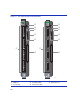
1-1 The 5H152-50 and 5H153-50 Modules ........................................................................... 1-2
3-1 Removing the Coverplate................................................................................................ 3-4
3-2 Installing the 5PIM........................................................................................................... 3-5
3-3 Different Physical Styles of GPIMs.................................................................................. 3-7
3-4 Installing a Side Clip GPIM into the 5PIM ....................................................................... 3-8
3-5 GPIM Metal Locking Bar Positions................................................................................ 3-11
3-6 Installing a Module into the 5C105 Chassis .................................................................. 3-14
3-7 Connecting a Twisted Pair Segment to the 5H152-50 .................................................. 3-16
3-8 Crossover Cable RJ45 Pinouts, Connection Between Hub Devices............................. 3-17
3-9 Straight-Through Cable RJ45 Pinouts, Connections
Between Switches and End User .................................................................................. 3-17
3-10 Connecting a Twisted Pair Segment to the 5H153-50 .................................................. 3-19
3-11 Connection Using Optional RJ21 Angle Adapter .......................................................... 3-20
3-12 Example of Cable Placement When Using Optional RJ21 Angle Adapters .................. 3-21
3-13 Fiber Port Designations................................................................................................. 3-22
3-14 GPIM-09 Launch Mode Conditioning Cable Connection............................................... 3-23
3-15 Fiber GPIM Connections ............................................................................................... 3-25
3-16 Fiber Port LED Designations......................................................................................... 3-26
4-1 LANVIEW LEDs (both modules) ..................................................................................... 4-2
4-2 RESET Button (same on both modules) ......................................................................... 4-7
B-1 Mode Switch Location .....................................................................................................B-2