
Installation guide


Installing Optional 5PIMs
3-5
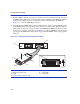
3.2.2 Installing the 5PIM
Refer to Figure 3-2 and proceed as follows:
1. Locate the standoff
➀ shipped with the 5PIM ➁ and screw it in place of the screw previously
removed from the board. Tighten the screw.
2. Position the 5PIM
➁ so its front panel is under the edge of the module front panel ➂.
3. Carefully align 5PIM connector
➃ with the module connector ➄. Then press straight down over
the 5PIM connector, applying pressure until it is properly seated into the module connector.
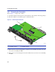
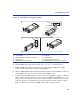
Figure 3-2 Installing the 5PIM
➀
Standoff
➃
5PIM connector
➅
Coverplate screws (2)
➁
5PIM
➄
Module connector
➆
Standoff screw
➂
Module front panel
À
Â
Ã
Ä
Å
Æ
36771-14
Á
1
2