
Installation guide


Installing Optional GPIMs
3-8
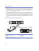
3. Hold the GPIM ➀ with the network port ➁ on the insertion end (not shown) facing away from
the 5PIM
➂. The 20-pin connector ➃ should be facing towards the empty GPIM slot, with the
wide part of the 20-pin connector oriented up in relation to the printing on the 5PIM. See
Figure 3-4 to orient the GPIM 20-pin connector.
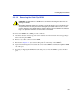
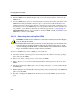
4. Carefully insert the GPIM (20-pin connector side) into the port slot
➄ of the GPIM. The top ➅
of the GPIM must be next to the hinge side of the slot door of the module. The door folds up
and the slides in the port slot engage the sides of the GPIM. If the GPIM does not insert easily,
do not force it. Check the orientation against Figure 3-5. Push the GPIM back until the 20-pin
port engages the GPIM. The locking tabs
➆ engage when the GPIM connector seats properly
in the port.
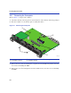
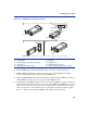
Figure 3-4 Installing a Side Clip GPIM into the 5PIM
➀
GPIM with side clip
➄
Hinged side of door
➁
Network connection end
➅
To p o f G P I M
➂
5PIM
➆
Locking tabs
➃
20-Pin connector (insertion end)
5PIM-G06
1
2
36771_17
Â
Ä
Ã
R
X
T
X
À
Á
Æ
Æ
Å