
Installation guide


Installing Optional GPIMs
3-11
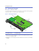
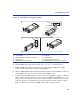
Figure 3-5 GPIM Metal Locking Bar Positions
2. Lift the GPIM metal locking bar ➂ upwards as far as it can go as shown in View A.
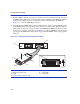
3. Hold the GPIM
➀ with the network port ➃ facing away from the 5PIM ➄. The 20-pin
connector
➅ should be facing towards the empty 5PIM slot ➆.
4. Align the GPIM
alignment slots ➇with the alignment guides inside the 5PIM slot ➆. The top
of the GPIM must be adjacent to the door hinge of the 5PIM slot door.
5. Carefully insert the GPIM ➀ (20-pin connector side) into the 5PIM slot opening ➆. The door
folds in and the slides engage the slots on the sides of the GPIM. If the GPIM does not go in
easily, do not force it into the slot. If it is not oriented correctly, it will stop about one quarter
of the way into the slot, and should not be forced any further. Check the orientation against
Figure 3-5. Remove and reorient the GPIM so that it slides easily into the slot.
➀
GPIM
➅
20-Pin connector (insertion side)
➁
To p o f G P IM
➆
5PIM slot
➂
Metal locking bar (up position, unlocked)
➇
Alignment slots
➃
Network port
➈
5PIM (installed in chassis)
➄
5PIM (Not installed in chassis)
➉
Metal locking bar (down position, locked)
Â
5PIM-G06
2
È
B
É
C
36772_16
A
5PIM-G06
2
Ç
Ä
Å
Â
Æ
Á
À
Ã