
Installation guide


Installing Optional GPIMs
3-12
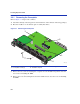
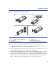
6. Push the GPIM ➀ back until the 20-pin connector port ➅ engages with the connector in the
5PIM slot
➆.
7. Once the GPIM 20-pin connector
➅ has been firmly seated into the module, push down on the
GPIM metal locking bar
➉until it clicks into place as shown in View B. Do NOT force the
locking bar into the locked position. If there is significant resistance while attempting to close
the locking bar, remove the GPIM. Inspect it for any problems with the connectors. If there are
any problems, contact Enterasys Networks for technical support (refer to “Getting Help” in
About This Guide). If there are no problems, re-insert the GPIM carefully, and firmly seat the
GPIM in the connector of the 5PIM.
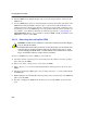
3.3.2.2 Removing the Locking Bar GPIM
To remove a GPIM from its slot in a 5PIM, proceed as follows:
1. Attach the antistatic wrist strap (refer to the instructions in the antistatic wrist strap package)
before removing the GPIM.
2. Remove any cables or dust protectors connected to the GPIM.
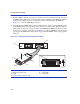
3. Refer to Figure 3-5. Locate the metal locking bar
➉in its locked position on the front of the
GPIM.
4. Lift the metal locking bar ➉upwards as far as it will go. See Figure 3-5, View A. This unlocks
the GPIM clips.
5. While holding the metal locking ➉bar in the upwards position, grasp the sides of the GPIM and
pull it out of the 5PIM.
6. If storing or shipping the GPIM, insert the dust protector into the GPIM to protect the fiber
ports.
CAUTION: Do NOT remove a GPIM from a slot without unlocking the metal locking bar.
This can damage the GPIM.
The GPIM, 5PIM, and module are sensitive to static discharges. Use an antistatic wrist
strap and observe all static precautions during this procedure. Failure to do so could
result in damaging the GPIM, 5PIM, or module. Always leave the GPIM in the antistatic
bag or an equivalent antistatic container when not installed.