
Installation guide


Installing the Module into the 5C105 Chassis
3-13
3.4 INSTALLING THE MODULE INTO THE 5C105 CHASSIS
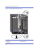
To install a module, refer to Figure 3-6 and proceed as follows:
1. Remove the blank panel covering the slot in which the module will be installed. All other slots
must remain covered to ensure proper airflow and cooling. (Save the blank plate in the event
you need to remove the module.)
2. Carefully remove the module from the shipping box. (Save the box and packing materials in the
event the module must be reshipped.)
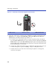
3. Locate the antistatic wrist strap shipped with the module. Attach the antistatic wrist strap to
your wrist and plug the cable from the antistatic wrist strap into the ESD grounding receptacle
at the upper right corner of the chassis.
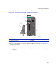
4. Remove the module from the plastic bag. (Save the bag in the event the module must be
reshipped.) Observe all precautions to prevent damage from Electrostatic Discharge (ESD).
5. Examine the module for damage. If any damage exists, DO NOT install the module.
Immediately contact Enterasys Networks. Refer to “Getting Help” in About This Guide.
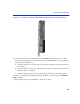
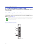
6. While referring to Figure 3-6, locate the card guides
➀ that line up with the slot number ➁ in
which the module card
➂ will be installed. Install the module in the chassis by aligning the
module card between the upper and lower card guides of the desired slot, sliding it into the
chassis, and locking down the top
➄ and bottom ➅ plastic locking tabs, as shown in Figure 3-6.
Take care that the module slides in straight and properly engages the backplane connectors
➆.
7. If the chassis in which the module is installed was powered down for the installation, turn it
back on. Check to see that the CPU LED settles at solid green after a few minutes. If the LED
does not turn solid green, see Chapter 4 for details.
CAUTION: Failure to observe static safety precautions could cause damage to the
module. Follow static safety handling rules and wear the antistatic wrist strap provided
with the 5C105 Chassis.
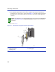
Do not cut the non-conductive bag to remove the module. Sharp objects contacting the
board or components can cause damage.
CAUTION: To prevent damaging the backplane connectors in the following step, take
care that the module slides in straight and properly engages the backplane connectors.
Ensure that the top plastic locking tab lines up with the desired slot number located on
the front panel of the chassis. Refer to Figure 3-6.