
Installation guide


Connecting to the Network
3-15
3.5 CONNECTING TO THE NETWORK
This section provides the procedures for connecting unshielded twisted pair (UTP) segments from
the network or other devices to the 5H152-50 (Section 3.5.1), or the 5H153-50 (Section 3.5.2). For
details on how to get manuals, refer to the “Related Documents” section in About This Guide.
3.5.1 Connecting UTP Cables to the 5H152-50
The fixed front panel ports of the 5H152-50 are 10/100 RJ45 ports with internal crossovers. When
connecting a workstation to these ports, use a straight-through cable. When connecting networking
devices to these ports, such as a bridge, repeater, or router, use a crossover cable.
Connect a twisted pair segment to the 5H152-50 as follows:
1. Ensure that the device connected to the other end of the segment is powered ON.
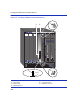
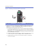
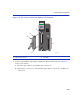
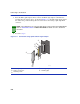
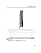
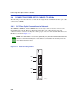
2. Refer to Figure 3-7 and connect the twisted pair segment to the 5H152-50 by inserting the RJ45
connector
➀ on the twisted pair segment into the appropriate RJ45 port connector ➁.
.
NOTE: If the module is being installed in a network using Port Trunking, there are rules
concerning the network cable and port configurations that must be followed for Port
Trunking to operate properly. Before connecting the cables, refer to the MATRIX E5
Series Modules Local Management User’s Guide for the configuration information.
NOTE: All RJ45 front panel ports on the 5H152-50 support Category 5 Unshielded
Twisted Pair (UTP) cabling with an impedance between 85 and 111 ohms. Category 3
cable may be used if the connection is going to be used only for 10 Mbps.