
Installation guide


Connecting to the Network
3-18
e. Ensure that the twisted pair connection meets the dB loss and cable specifications outlined
in the Cabling Guide. Refer to “Getting Help” in About This Guide for information on
obtaining this document.
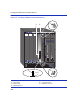
4. If a link is not established, contact Enterasys Networks. Refer to “Getting Help” in About This
Guide for details.
5. Repeat all the steps above until all connections have been made.
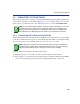
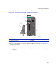
3.5.2 Connecting UTP Cables to the 5H153-50
When facing the front panel of the 5H153-50, the RJ21 connectors from top to bottom represent
Ethernet/Fast Ethernet segments 1 through 12, segments 13 through 24, 25 through 36, and 37
through 48, respectively.
To connect a UTP segment to the 5H153-50, proceed as follows:
1. Ensure that the device connected to the other end of the segment is powered ON.
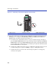
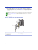
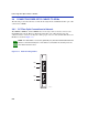
2. If using an RJ21 straight connector
➀, refer to Figure 3-10 and proceed as follows:
a. Plug the RJ21 straight connector
➀ into the appropriate RJ21 port connector ➁.
b. Tighten the two screws
➂ to secure the RJ21 straight connector ➀ to the RJ21 port
connector
➁.
c. Proceed to step 4.
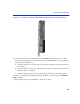
NOTE: The cable pinouts for a 25-pair cable (RJ21) can be found in the Cabling Guide.
Refer to “Related Documents” in About This Guide for details on how to obtain this
document.