
Installation guide


Connecting Fiber Optic Cables to GPIMs
3-25
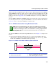
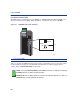
Figure 3-15 Fiber GPIM Connections
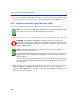
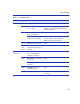
3. At the other end of the fiber optic cable, attach the SC connector to the other device. Verify that
a link exists by checking that the port Receive LED (RX), shown in Figure 3-16, is ON
(flashing amber, blinking green, or solid green). Refer to Chapter 4 for details on the LEDs. If
the Receive LED is OFF and the Transmit LED (TX) is not blinking amber, perform the
following steps until it is ON:
a. Check that the device at the other end of the link has power turned on and is Gigabit
Ethernet compatible.
b. Verify proper crossover of fiber strands between the port on the module and the fiber optic
device at the other end of the fiber optic link segment.
c. Verify that the fiber optic cable meets the specifications outlined in Appendix C for the
installed GPIM.
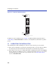
To remove the SC connector from the GPIM, carefully pull the connector out of the port. It may
need to be wiggled gently to release the latching keys.
➀
SC cable connector
➂
GPIM-01, GPIM-08, or GPIM-09
➁
Latch keys (bottom of SC connector)
➃
5PIM interface module
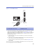
Â
3677_19
Ã
Á
À
SC Connector
2
1
5PIM-G06