
Installation guide

Figures ix
Figures
Figure Page
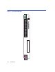
1-1 The 6H352-25 Module.....................................................................................................1-2
3-1 Installing the 6H352-25 into the MATRIX E7 Chassis..................................................... 3-4
3-2 Installing the 6H352-25 into the SmartSwitch 6000 Chassis........................................... 3-6
3-3 Connecting a Twisted Pair Segment to the 6H352-25 ....................................................3-8
3-4 Crossover Cable RJ45 Pinouts ....................................................................................... 3-9
3-5 Straight-Through Cable RJ45 Pinouts.............................................................................3-9
4-1 LANVIEW LEDs ..............................................................................................................4-2
4-2 RESET Button.................................................................................................................4-7
B-1 Mode Switch Location .....................................................................................................B-2
B-2 FLASH Memory Location ................................................................................................B-4
B-3 Installing the FLASH Memory..........................................................................................B-5
B-4 HSIM and VHSIM Connector Locations..........................................................................B-6