
Installation guide

Connecting to the Network
Matrix DFE-Diamond Series Installation Guide 3-13
ADFEmodulecanbeinstalledinanyavailablechassisslot:1through3intheMatrix N3chassis,
thesingleslotoftheN1chassis,or1through5intheMatrix N5chassis.Allchassishave
horizontalslotsforDFEmodules.ToinstallaDFEmoduleintotheMatrixN3,N1,
orN5chassis,
refertoFigure 3‐7and use theinstallationproceduredescribedin“InstallingModuleinto
Matrix E7orN7Chassis”onpage 3‐10.
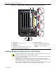
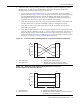
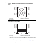
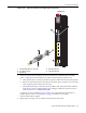
Figure 3-7 Installing Module into Matrix N3, N1, or N5 Chassis (Matrix N3 shown)
Connecting to the Network
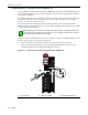
Thissectionprovidestheproceduresforconnectingunshieldedtwistedpair(UTP)segmentsfrom
thenetworkorotherdevicestothe7GR4202‐30(“ConnectingUTPCablestothe7GR4202‐30”on
page 3‐14).ForconnectionstoMini‐GBICportsonthe7GR4270‐12ortheoptionalNEM,referto
“Connecting
Fiber‐OpticCablestoMini‐GBICs”onpage 3‐17.
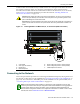
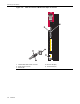
Caution: When setting the locking levers to the closed position, do not try to force the locking
levers to the point that they touch the face of the front panel. Forcing the locking levers to this
point could damage the module and chassis.
Precaución: Al mover las palancas a la posición de cerrado, tenga cuidado de no llevarlas a un
punto en donde estén en contacto con el panel frontal. Si lo hace, podría dañar el módulo o el
chasis.
1 Card guides 5 Upper locking tab (shown in closed position)
2 Slot 1 (Top slot is slot 3.) 6 Lower locking tab (shown in closed position)
3 Module card 7 FTM2 backplane connectors
4 Metal back panel
7GR4280-19
Note: If the DFE module is being installed in a network using Link Aggregation, there are rules
concerning the network cable and port configurations that must be followed for Link Aggregation to
operate properly. Before connecting the cables, refer to the Enterasys Matrix DFE-Diamond/
Platinum Series Configuration Guide for the configuration information. For details on how to obtain
manuals, refer to the “Related Documents”
in About This Guide.