
Installation guide


Memory Locations and Replacement Procedures
Matrix DFE-Diamond Series Installation Guide B-3
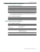
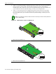
Figure B-3 Mode Switch Location on the 7GR4280-19
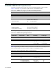
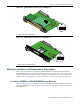
Figure B-4 Mode Switch Location on the 7KR4290-02
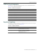
Memory Locations and Replacement Procedures
IntheeventthattheDualinLineMemoryModule(DIMM)orDRAMSingleIn‐lineMemory
Module(SIMM)needstobereplaced,thefollowingsectionsdescribehowtoaccess,locate,and
replacethesememorymodules.Ifyouhavequestionsconcerningthereplacementofthememory
modules,referto“Getting
Help”onpage xvfordetailsonhowtocontactEnterasys Networks.
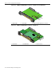
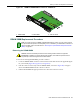
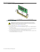
Location of DIMM and DRAM SIMM Memory Modules
Figure B‐5throughFigure B‐7showthelocationsoftheDIMMandDRAMSIMMoneachmain
board.The7GR4270‐12isshowninFigure B‐5.However,theapproximatelocationalsoappliesto
the7GR4202‐30.
1 Mode switch pack (7GR4280-19)
1 Mode switch bank (7KR4290-02)