™ ENJOY THE FREEDOM OF WIRELESS NETWORKING Access Point 2000 Hardware Installation Guide ENTERASYS.
ELECTRICAL HAZARD: Only qualified personnel should perform installation procedures. NOTICE Enterasys Networks reserves the right to make changes in specifications and other information contained in this document and its web site without prior notice. The reader should in all cases consult Enterasys Networks to determine whether any such changes have been made. The hardware, firmware, or software described in this document is subject to change without notice.
Notice FCC Notice Note: This equipment has been tested and found to comply with the limits for a Class B digital device, pursuant to part 15 of the FCC Rules. These limits are designed to provide reasonable protection against harmful interference in a residential installation. This equipment generates, uses and can radiate radio frequency energy and, if not installed and used in accordance with the instructions, may cause harmful interference to radio communications.
Notice ENTERASYS NETWORKS, INC. PROGRAM LICENSE AGREEMENT BEFORE OPENING OR UTILIZING THE ENCLOSED PRODUCT, CAREFULLY READ THIS LICENSE AGREEMENT. This document is an agreement (“Agreement”) between the end user (“You”) and Enterasys Networks, Inc.
Notice (v) Remove any copyright, trademark, proprietary rights, disclaimer or warning notice included on or embedded in any part of the Program. 3. APPLICABLE LAW. This Agreement shall be interpreted and governed under the laws and in the state and federal courts of the Commonwealth of Massachusetts without regard to its conflicts of laws provisions. You accept the personal jurisdiction and venue of the Commonwealth of Massachusetts courts.
Notice 7. LIMITATION OF LIABILITY. IN NO EVENT SHALL ENTERASYS OR ITS SUPPLIERS BE LIABLE FOR ANY DAMAGES WHATSOEVER (INCLUDING, WITHOUT LIMITATION, DAMAGES FOR LOSS OF BUSINESS, PROFITS, BUSINESS INTERRUPTION, LOSS OF BUSINESS INFORMATION, SPECIAL, INCIDENTAL, CONSEQUENTIAL, OR RELIANCE DAMAGES, OR OTHER LOSS) ARISING OUT OF THE USE OR INABILITY TO USE THE PROGRAM, EVEN IF ENTERASYS HAS BEEN ADVISED OF THE POSSIBILITY OF SUCH DAMAGES.
Notice 13. SEVERABILITY. In the event any provision of this Agreement is found to be invalid, illegal or unenforceable, the validity, legality and enforceability of any of the remaining provisions shall not in any way be affected or impaired thereby, and that provision shall be reformed, construed and enforced to the maximum extent permissible.
Contents Preface Purpose of the Manual . . . . . . . . . . . . . . . . . . . . . . . . . . . . . . . . . . . . . . . . . . . . . . . . . . . . . . . ix Intended Audience . . . . . . . . . . . . . . . . . . . . . . . . . . . . . . . . . . . . . . . . . . . . . . . . . . . . . . . . . . ix Organization of this Document . . . . . . . . . . . . . . . . . . . . . . . . . . . . . . . . . . . . . . . . . . . . . . . . ix Document Conventions . . . . . . . . . . . . . . . . . . . . . . . . . . . . . . . . . . . .
Table of Contents 2 Cabling and Wiring Selecting a Power Configuration . . . . . . . . . . . . . . . . . . . . . . . . . . . . . . . . . . . . . . . . . . . . . . Local Power Configuration. . . . . . . . . . . . . . . . . . . . . . . . . . . . . . . . . . . . . . . . . . . . . . . Remote Power Configuration . . . . . . . . . . . . . . . . . . . . . . . . . . . . . . . . . . . . . . . . . . . . . Redundant Power Configuration . . . . . . . . . . . . . . . . . . . . . . . . . . . . . . . . . . . . . . . . .
Preface Purpose of the Manual This manual describes how to install and set up the RoamAbout Access Point 2000. It also includes problem solving, and connector pin assignment information. Intended Audience This manual is intended for use by personnel who will install and set up the RoamAbout Access Point 2000. ELECTRICAL HAZARD: Only qualified personnel should perform installation procedures.
Preface Document Conventions The following icons are used in this document: Icon Meaning ELECTRICAL HAZARD: Warns against an action that could result in personal injury or death. CAUTION: Contains information essential to avoid damage to the equipment. NOTE: Calls the reader’s attention to any item of information that may be of special importance.
Preface Associated Documents The following table lists the RoamAbout products and information location. The documentation, drivers, and utilities can also be downloaded from the RoamAbout Wireless web site. Check the RoamAbout Wireless web site regularly for product upgrades. www.enterasys.com/wireless Component Information Location All RoamAbout components RoamAbout 802.11 Wireless Networking Guide RoamAbout AP Manager AP Manager online help RoamAbout 802.11b PC Card and drivers RoamAbout 802.
Preface Getting Help For additional support related to this device or document, contact Enterasys Networks using one of the following methods: World Wide Web: Phone: www.enterasys.com/support (603) 332-9400 1-800-872-8440 (toll-free in the U.S. and Canada) For the Enterasys Networks Support toll-free number in your country: Internet mail: www.enterasys.com/support/gtac-all.html support@enterasys.
Chapter 1 Preparing for Installation This chapter describes basic considerations for successfully installing the RoamAbout Access Point 2000 hardware. Before installing the Access Point (AP), you must complete the following tasks: • Review the site requirements. • Select the location to install the AP. • Unpack the AP and check the contents of the shipment.
Reviewing the Site Requirements Reviewing the Site Requirements Please review the site requirements before you install the Access Point. Hardware Requirements Table 1-1: AP Physical Specifications (with plastic cover) Parameter Access Point Width 17.9 cm (7.06 in) Height 16.8 cm (6.64 in) Depth 4.1 cm (1.63 in) Weight .86 kg (1.9 lb) Environmental Requirements Ensure that the environmental requirements are within the ranges described in Table 1-2.
Reviewing the Site Requirements Electrical Requirements The Access Point 2000 power and connector specifications are listed in Table 1-3. These specifications are provided for customers who want to provide their own site operating power for the Access Point 2000. If the remote power feature is used, you must test the Ethernet cable from the remote power injector to the Access Point 2000 for continuity and correct pinout before power is applied.
Unpacking and Inspecting Unpacking and Inspecting Physically inspect all cartons for shipping damage. Report any damage to your shipping carrier. Also verify that you have received the correct basic components and options as listed on the following pages. Report any discrepancies to your Enterasys Sales Representative. Basic Components The basic components required for installation include an Access Point and a PC Card.
Unpacking and Inspecting Access Point Verify that the following components shipped with your Access Point: # Description Part Number 1, 2 RoamAbout Access Point 2000 (with wall/ceiling mounting bracket) CSIWS-A 3 Plastic Cover 8520216-01 NOTE: A security box, sold separately, is available. Contact your Enterasys Representative for more information.
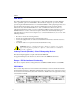
Options Options The following options are available for the Access Point: 1 2 4 3 APH_02 # Description Part Number 1 Redundant (or replacement) Power Supply (with four International Power Adapters) RBTR2-PS3 2 Rack Mount Kit CSIWS-RM 3 Range Extender Antenna CSIBB-IA 4 Security Box CSIWS-WM Other Considerations Enterasys Networks recommends that you test the coverage area before you permanently install the Access Point.
Chapter 2 Cabling and Wiring This chapter presents detailed step-by-step procedures to select, configure, and install the correct power, cabling, and wiring for your RoamAbout Access Point 2000. CAUTION: The Enterasys 5652054-xx International DC Power Supply (ships with the RoamAbout Access Point 2000) and the RBTR2-PS3 Redundant DC Power Supply have overload protection.
Selecting a Power Configuration Selecting a Power Configuration The power configurations available for the Access Point include local power, remote power, and redundant power. Local Power Configuration In the local power configuration, the AP receives operating power directly from one local source (such as a power module connected to a nearby wall outlet). The output plug of the power module is connected directly into the AP chassis-mounted power connector.
Remote Power Injector Installation Remote Power Injector Installation The remote power injector provides operating power to the AP using the Ethernet cable. The injector receives input power (via the PWR jack) from either the power module supplied with the AP or directly from the site facility. If using the power module, install the injector within six feet of an AC power outlet. The network interface cable plugs into the NETWORK jack, and the Access Point cable plugs into the ROAMABOUT AP jack.
Remote Power Injector Installation Use the following procedure to install the remote power injector. 1. If available, use a cable tester to check the cable wiring to the AP. Check continuity and pairing. 2. Select a mounting location: — Close to the Ethernet wiring panel or Ethernet port. — Within six feet of an AC power outlet (if remote power is used). 3. Secure the remote power injector. If necessary, use the two wall anchors provided in your installation kit. Mounting Hole (2) 4.
Rack Mount Kit Installation Rack Mount Kit Installation The rack mount kit allows you to install up to three remote power injectors into one standard rack-mount panel to provide for the operation of up to three APs. The information presented in the Remote Power Injector Installation on page 2-3 applies to each of the three remote power injectors in the rack mount kit. Use the following procedure to install the rack mount kit. 1. If available, use a cable tester to check the cable wiring to each AP.
Power Module Installation Power Module Installation To install the 100-240VAC power supply, perform the following steps: 1. Verify that you have the correct power supply connector. USA (NEMA 5-15 TO IEC-C13) L E N EU (CEE7 TO IEC-C13) UK (UK TO IEC-C13) AU (AS3112 TO IEC-C13) R2_06 2. Insert the appropriate connector into the power supply. CAUTION: Do not connect the power supply to the primary source until instructed to do so. R2_07 CAUTION: You must use a UL Listed Class 2 power supply.
Selecting the Correct Ethernet Wiring Configuration Selecting the Correct Ethernet Wiring Configuration If you have an existing 10BaseT Ethernet cable in place, you can connect the cable directly to the Access Point. You can also connect the Ethernet cable to the remote power injector, then connect the remote power injector to the AP. To ensure correct system operation, make sure you select the appropriate straight-through or crossover Ethernet wiring configuration for your installation.
Power and Connector Specifications Power and Connector Specifications Access Point power and connector specifications are listed in the table below. These specifications are provided for customers who want to provide their own site operating power for the AP. If the remote power feature is used, Enterasys strongly recommends that you test the cable from the remote power injector to the AP for continuity and correct pinout (straight-through cable) before power is applied.
Chapter 3 Installing the Access Point This chapter provides the procedures to install the Access Point 2000 and its options. Make sure the site primary power for the AP conforms to the specifications detailed in Chapter 2. If using a BootP/TFTP server and the AP Manager to configure the APs with IP addresses, you should configure the server BEFORE applying power to each AP. Upon power-up, each AP automatically sends a BootP request.
Wall/Ceiling Outlet Box Installation Wall/Ceiling Outlet Box Installation Follow the step-by-step procedure below to install the Access Point to an outlet box. 1. Make sure the site primary power for the AP conforms to the specifications detailed in Chapter 2 - Cabling and Wiring. 2. Select a wall or ceiling outlet: — If using remote power, with internal 10BaseT Ethernet network cabling installed.
Wall/Ceiling Outlet Box Installation 4. Connect the Ethernet cable. 5. Before installing the metal mounting bracket, make certain that the mounting holes on the bracket line up with those on the outlet box. Additional holes may be drilled in the bracket to accommodate your particular installation. NOTE: Remove all drilled material from the area. 6. Secure the mounting bracket to the wall outlet box. 7.
Wall/Ceiling Outlet Box Installation 8. Install the PC Card: — Position the card as shown below. — Carefully insert the card. — Press down firmly to seat the card.
Wall/Ceiling Outlet Box Installation 9. If you install the optional range extender antenna or outdoor antenna: — Remove the dust cover. — Insert the antenna plug into the PC Card connector. — Gently press down on the plug to secure the antenna connection. APH_25G 10. Install the remote power injector or the rack mount kit, if used. Refer to Remote Power Injector Installation on page 2-3 or Rack Mount Kit Installation on page 2-5.
Wall/Ceiling Outlet Box Installation 11. Install the power module/redundant power module, if used. Refer to Power Module Installation on page 2-6. Connect the output of the power module/redundant power module to the AP. S1 S2 12. Connect the power module into an AC outlet. 13. Verify power on by observing that some of the AP LEDs are flashing or lit. APH_27 14. Secure the cover: — Position the cover over the AP. — Make sure the cover clears the antenna plug.
Surface Wallmount Installation Surface Wallmount Installation Follow the step-by-step procedure below to install the AP on the surface of a wall, cubical wall, vertical support structure, or ceiling. 1. Make sure the site primary power for the AP conforms to the specifications detailed in Chapter 2 - Cabling and Wiring. 2. Select the optimum mounting location: — With easy access for inspection and service. — If using remote power, close to the 10BaseT Ethernet network cable connector.
Surface Wallmount Installation 4. Flatten the metal mounting bracket tab against the bracket, or remove the tab by bending it back and forth. Tab APH_29 5. Secure the mounting bracket to the wall: — Locate at least two mounting holes/slots on the mounting bracket that line up with a wall stud. — Use two screws to secure the mounting bracket to the wall stud. — Use plastic anchors and screws, or self-anchoring screws to secure the mounting bracket to the wallboard.
Surface Wallmount Installation 6. Secure the AP to the mounting bracket: — Insert the two AP shoulder screws into the two mounting bracket screw slots. — Slide the AP down. — Tighten the captive screw to secure the AP.
Surface Wallmount Installation 7. Install the PC Card: — Position the card as shown below. — Carefully insert the card. — Press down firmly to seat the card.
Surface Wallmount Installation 8. If you install the optional range extender antenna or outdoor antenna: — Remove the dust cover. — Insert the antenna plug into the PC Card connector. — Gently press down on the plug to secure the antenna connection. APH_25G 9. Install the remote power injector or the rack mount kit, if used. Refer to Remote Power Injector Installation on page 2-3 or the Rack Mount Kit Installation on page 2-5.
Surface Wallmount Installation 10. Connect the 10BaseT Ethernet network cable. If you are using the remote power feature, label the end of the cable to the AP with: CAUTION: Ethernet cable contains power. Do not use for other devices. If you are not using remote power, install the power module/redundant power module, if used; refer to Power Module Installation on page 2-6. S1 11. Connect the power module into an AC outlet. 12. Verify power on by observing that some of the AP LEDs are flashing or lit.
Surface Wallmount Installation 13. Secure the cover: — Position the cover over the AP. — Make sure the cover clears the antenna plug. — Push the cover down until all four snaps are secured.
Desktop Installation Desktop Installation To install the Access Point on a desktop, do the following: 1. Make sure the site primary power for the AP conforms to the specifications detailed in Chapter 2 - Cabling and Wiring. 2. Select a desktop location: — If using remote power, close to the 10BaseT Ethernet network cable connector. — If not using remote power, within five feet of an AC electrical outlet: a) If using redundant power (connecting both local power and remote power).
Desktop Installation 4. Remove the captive screw bracket by removing two screws. Screw (2) Bracket 5. Re-install the two screws. 6. Install the four rubber feet on the bottom of the AP. NOTE: Exact placement of each rubber foot is not crucial. For maximum stability, install each rubber foot as close to a corner of the AP as possible.
Desktop Installation 7. Install the PC Card: — Position the card as shown below. — Carefully insert the card. — Press down firmly to seat the card.
Desktop Installation 8. If you install the optional range extender antenna or outdoor antenna: — Remove the dust cover. — Insert the antenna plug into the PC Card connector. — Gently press down on the plug to secure the antenna connection. APH_25G 9. Install the remote power injector or the rack mount kit, if used. Refer to Remote Power Injector Installation on page 2-3 or the Rack Mount Kit Installation on page 2-5.
Desktop Installation 10. Connect the 10BaseT Ethernet network cable. If you are using the remote power feature, label the end of the cable to the AP with: CAUTION: Ethernet cable contains power. Do not use for other devices. If you are not using remote power, install the power module/redundant power module, if used; refer to Power Module Installation on page 2-6. S1 11. Connect the power module into an AC outlet. 12. Verify power on by observing that some of the AP LEDs are flashing or lit.
Desktop Installation 13. Secure the cover: — Position the cover over the AP. — Make sure the cover clears the antenna plug. — Push the cover down until all four snaps are secured.
Connecting a Device to the Console Port Connecting a Device to the Console Port You can manage the Access Point using its console port or using the RoamAbout AP Manager program. You do not need to use the console port if you use the AP Manager. These management tools are described in the RoamAbout 802.11 Wireless Networking Guide. You can connect a terminal or personal computer running terminal emulation software to the console port.
Connecting a Device to the Console Port e) In the Port Settings window, enter: — Bits per second: 9600 — Data bits: 8 — Parity: None — Stop Bits: 1 — Flow Control: Hardware To connect to the console port at a later date, open Hyperterminal and select File→Open to open the AP Console Port connection. 5. Press a few times until the RoamAbout Access Point Installation Menu is displayed. The installation menu allows you to display and modify various AP and wireless networking parameters.
Verifying the Operation of the Access Point Verifying the Operation of the Access Point The Access Point runs a series of self-tests on power-up and reports status using its LEDs (shown below). The diagnostics take several seconds to complete after power-up. Table 31 describes the LEDs. If the AP LEDs indicate an error, verify that you have correctly installed the AP. Table 3-2 describes the patterns, the most likely causes, and possible corrective actions.
Verifying the Operation of the Access Point Table 3-1: Access Point LED Summary Table Name Description Power/System OK Lights when the AP has power and has passed the self-test. If the AP fails the test, the LED blinks at a steady rate. Bridge State Lights when the AP is forwarding packets. 1 Access Point Saturated 2 Wireless LAN Activity Lights when the AP is saturated.
Verifying the Operation of the Access Point Table 3-2: Access Point LED Patterns Wired LAN Wireless LAN Access Point Saturated 2 Bridge State Power/ System OK Meaning of LED Pattern 1 No power. Check the power connections. Diagnostics failed. The AP automatically resets after one minute. If the pattern continues to display, contact technical support. Normal operating mode. AP is waiting for the spanning tree. No action is required. Or, Spanning Tree detected a bridge loop and disconnected the port.
Configuring the Access Point Configuring the Access Point If creating a new wireless network, refer to the RoamAbout 802.11 Wireless Networking Guide for the complete configuration procedures. If adding this Access Point to an existing wireless infrastructure network, the following sections provide the basic procedure to configure the AP. Refer to the RoamAbout 802.11 Wireless Networking Guide for details. Using the RoamAbout AP Manager 1.
Configuring the Access Point Using the RoamAbout AP Console Port 1. Press the key at the terminal that is connected to the console port until the RoamAbout Access Point Installation Menu appears. If using a computer, start the terminal emulation program and connect to the console port. 2. To allow the AP Manager or other management tools using SNMP to remotely manage the AP, perform the following: a) Choose Set IP Address from the Installation Menu.
Appendix A Upgrade and Reset This appendix describes how to upgrade the RoamAbout Access Point 2000 firmware using the console port or AP Manager. It also describes how to reset the R2 to all factory defaults. Check the Enterasys Networks Wireless web site for the latest RoamAbout AP Manager and firmware. Go to www.enterasys.com/wireless and click on the Software Download Library to download the latest AP Manager and RoamAbout Access Point 2000 firmware.
Upgrade Firmware Upgrade Firmware Using the Console Port Follow this procedure to upgrade the Access Point 2000 from the console port. Do not choose the Save command when using the Upgrade Flash command. 1. Choose Module-Specific Options from the Access Point Installation Menu. 2. Choose Upgrade Flash from the next menu. 3. Choose BootP Server if a BootP server has been configured with the correct file. Choose TFTP Server if you wish to upgrade the AP with a specific image.
Upgrade Firmware 4. If the remote BootP option was not selected, use the Browse button next to the File field to locate the latest N*.BIN file for firmware upgrades or R*.BIN file for BootROM upgrades. 5. Click on the Reload Now button. NetRider Loader starts (if you did not specify to use your TFTP server). 6. Click Yes to confirm the upgrade, then click OK to reconfirm the upgrade. 7. AP Manager displays a Poll dialog box that prompts you to poll the AP. Polling lets you know when the upgrade is complete.
Hardware Reset to Factory Defaults Hardware Reset to Factory Defaults The RoamAbout Access Point 2000 hardware reset button (labeled S1 on the unit) forces the AP to download a firmware image and reset to factory default values. Use the reset button when you are unable to reload or upgrade the AP using the AP Manager or console port (i.e., should the AP firmware suffer data corruption).
Hardware Reset to Factory Defaults 7. Reapply power then press the reset button (S1) on the AP. If an image is not available, the AP waits approximately three minutes then resets to factory default values. NetRider Loader indicates a loading status. CAUTION: The NetRider Loader application only indicates when the file copy is completed, it does not indicate when the upgrade is complete. 8. Click on Close to exit NetRider Loader when the loading is complete. 9. View the console screen.