
User`s guide


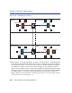

Table Of Contents
- Title
- Notice
- Contents
- Figures
- Tables
- About This Guide
- Introduction
- Local Management Requirements
- Accessing Local Management
- 3.1 Navigating Local Management Screens
- 3.2 Password Screen
- 3.3 Main Menu Screen
- 3.4 Module Selection Screen
- 3.5 Module Menu Screen
- 3.6 Overview of Security Methods
- 3.7 Security Menu Screen
- 3.8 Passwords Screen
- 3.9 Radius Configuration Screen
- 3.10 Name Services Configuration Screen
- 3.11 System Authentication Configuration Screen
- 3.12 EAP (Port) Configuration Screen
- 3.13 EAP Statistics Menu Screen
- 3.14 MAC Port Configuration Screen
- 3.15 MAC Supplicant Configuration Screen
- Chassis Menu Screens
- 4.1 Chassis Menu Screen
- 4.2 Chassis Configuration Screen
- 4.3 SNMP Configuration Menu Screen
- 4.4 SNMP Community Names Configuration Screen
- 4.5 SNMP Traps Configuration Screen
- 4.6 Chassis Environmental Information Screen
- 4.7 Redirect Configuration Menu Screen (Chassis)
- 4.8 Port Redirect Configuration Screen
- 4.9 VLAN Redirect Configuration Screen
- Module Configuration Menu Screens
- 5.1 Module Configuration Menu Screen
- 5.2 General Configuration Screen
- 5.2.1 Setting the IP Address
- 5.2.2 Setting the Subnet Mask
- 5.2.3 Setting the Default Gateway
- 5.2.4 Setting the TFTP Gateway IP Address
- 5.2.5 Setting the Module Name
- 5.2.6 Setting the Module Date
- 5.2.7 Setting the Module Time
- 5.2.8 Entering a New Screen Refresh Time
- 5.2.9 Setting the Screen Lockout Time
- 5.2.10 Configuring the COM Port
- 5.2.11 Clearing NVRAM
- 5.2.12 Enabling/Disabling IP Fragmentation
- 5.3 SNMP Configuration Menu Screen
- 5.4 SNMP Community Names Configuration Screen
- 5.5 SNMP Traps Configuration Screen
- 5.6 Access Control List Screen
- 5.7 System Resources Information Screen
- 5.8 FLASH Download Configuration Screen
- Port Configuration Menu Screens
- 6.1 Port Configuration Menu Screen
- 6.2 Ethernet Interface Configuration Screen
- 6.3 Ethernet Port Configuration Screen
- 6.4 HSIM/VHSIM Configuration Screen
- 6.5 Redirect Configuration Menu Screen
- 6.6 Port Redirect Configuration Screen
- 6.7 VLAN Redirect Configuration Screen
- 6.8 Link Aggregation Screen (802.3ad Main Menu Screen)
- 6.9 Broadcast Suppression Configuration Screen
- 802.1 Configuration Menu Screens
- 802.1Q VLAN Configuration Menu Screens
- 8.1 Summary of VLAN Local Management
- 8.2 802.1Q VLAN Configuration Menu Screen
- 8.3 Static VLAN Configuration Screen
- 8.4 Static VLAN Egress Configuration Screen
- 8.5 Current VLAN Configuration Screen
- 8.6 Current VLAN Egress Configuration Screen
- 8.7 VLAN Port Configuration Screen
- 8.8 VLAN Classification Configuration Screen
- 8.9 Protocol Port Configuration Screen
- 802.1p Configuration Menu Screens
- 9.1 802.1p Configuration Menu Screen
- 9.2 Port Priority Configuration Screen
- 9.3 Traffic Class Information Screen
- 9.4 Traffic Class Configuration Screen
- 9.5 Transmit Queues Configuration Screen
- 9.6 Priority Classification Configuration Screen
- 9.7 Protocol Port Configuration Screen
- 9.8 Rate Limiting Configuration Screen
- Layer 3 Extensions Menu Screens
- Module Statistics Menu Screens
- Network Tools Screens
- VLAN Operation and Network Applications
- 13.1 Defining VLANs
- 13.2 Types of VLANs
- 13.3 Benefits and Restrictions
- 13.4 VLAN Terms
- 13.5 VLAN Operation
- 13.6 Configuration Process
- 13.7 VLAN Switch Operation
- 13.8 VLAN Configuration
- 13.9 Summary of VLAN Local Management
- 13.10 Quick VLAN Walkthrough
- 13.11 Examples
- 13.12 Example 1, Single Switch Operation
- 13.13 Example 2, VLANs Across Multiple Switches
- 13.14 Example 3, Filtering Traffic According to a Layer 4 Classification Rule
- 13.15 Example 4, Securing Sensitive Information According to Subnet
- 13.16 Example 5, Using Dynamic Egress to Control Traffic
- 13.17 Example 6, Locking a MAC Address to a Port Using Classification Rules
- Generic Attribute Registration Protocol (GARP)
- About IGMP
- Index
Example 2, VLANs Across Multiple Switches
VLAN Operation and Network Applications 13-29
13.13.2 Frame Handling
The following describes how, when User A attempts to log on to the File Server on Bridge 4, the
frames from User A are classified on Switch 4 and traverse the network. In this example, the MAC
address of User A is “Y” and the MAC address for the File Server is “Z”. The following
description includes illustrations to help understand how the frames flow through the network.
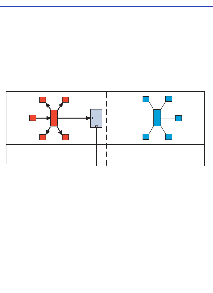
1. User A sends a frame with a Broadcast Destination Address in an attempt to locate the File
Server. The frame is received on User A’s port of Bridge 1 and, because the frame is a broadcast
frame, it is transmitted out all ports of Bridge 1 as shown in Figure 13-13.
Figure 13-13 Bridge 1 Broadcasts Frames
2. Switch 4 receives the frame from Bridge 1 and immediately classifies it as belonging to the Red
VLAN. After the frame is classified, Switch 4 checks the Destination Address and, upon
discovering that it is a Broadcast Destination Address, forwards the frame out all ports in the
Red VLAN Forwarding List excluding Port 1, which received the frame. In this example, it is
only Port 4.
Switch 4 updates its Source Address Table in FDB ID 2 if it didn’t already have a dynamic entry
for MAC address “Y” in FDB ID 2. Because Switch 4 received the frame on Port 1, it does not
forward the frame out that port, but does forward the frame to Port 4.
The frame is transmitted to Switch 2 with a VLAN Tag Header inserted in the frame. The VLAN
Tag Header indicates that the frame is classified as belonging to the Red VLAN. Figure 13-14
shows the path taken to this point to reach Switch 2.
The VLAN Tag Header is inserted because Switch 4, Port 4 is set to transmit tagged frames.
Floor 4
2263_14
1
3
2
Bridge 1
Bridge 2
Redco Blue Industries
Red VLAN
Red VLAN
Blue VLAN
Blue VLAN
User A
4
4