
User's Manual


CHAPTER 8 INTERFACE CONTROL DOCUMENTS (ICD)
APPENDIX A INTERFACE CONTROL DOCUMENTS (ICD)
ISSUE/REVISION DATE: 25 JULY 2007 TECHNICAL MANUAL
ISO 9001:2000 PROPRIETARY
Interface Control Document (ICD) ENTERPRISE ELECTRONICS CORPORATION
Rev No. 5 Page 8 of 21
Issue Date 25 July 2007 UM-130365
Distribution Data Collection
Module (DDC)
THE DATA PRESENTED HEREIN REPRESENTS THE INTELLECTUAL PROPERTY OF ENTERPRISE ELECTRONICS CORPORATION (EEC). THIS DATA MAY NOT BE DISTRIBUTED OR REPRODUCED BY
ANY MEANS WITHOUT THE EXPRESS, WRITTEN CONSENT OF EEC.
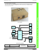
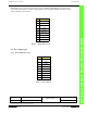
JP1-JP4
JP1-JP4 LOCATION
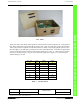
The eight buffered TTL outputs are connected to the 37 pin D connector, J4, visible in Figure 4.
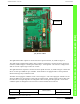
The eight analog to digital inputs (ADC) with a resolution of 10 bits are connected to the 37 pin D con-
nector J3, visible in Figure 3. Each input is filtered by a .1 mF capacitor. The reference voltage for the
ADC is 5.0 volts. Input range is from 0 to +5 VDC.
The eight Sink Driver outputs are connected to the 37 pin D connector, J3, visible in Figure 3. Each sink
driver can sink up to 500ma at up to +24VDC. Each sink driver is equipped with a current protection
diode for driving relays or inductive loads.
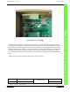
The DDC auto-ranging DC voltmeter circuit is seen in Figure 5. The auto-ranging DC voltmeter circuit
allows the DDC to be connected to a wide range of bi-polar inputs. Voltage inputs can be bi-polar from
0 to 200 volts. The input impedance is 1 Meg Ohm. There are 8 inputs and 2 grounds. Access to the
voltmeter inputs are through the J2 10-circuit screw down terminal block connector.