EMG Ethernet Modbus Gateway User Manual Rev 2.
CONTENTS 1. Introduction 1.1. General Features 1.2 Installing the Drivers 2. Configuration 2.1 Main Device Parameters 2.1.1 RS485 Serial Communication Parameters 2.1.1.1 Baud Rate 2.1.1.2 Data Bit 2.1.1.3 Stop Bit 2.1.1.4 Parity Bit 2.1.1.5 Time-Out 2.1.1.6 Delay 2.1.2 Network Parameters 2.1.2.1 Connection Settings 2.1.2.2 DHCP 2.1.2.3 WEB Access 2.1.2.4 WEB Port 2.1.2.5 Log-in Timeout 2.1.2.6 Server IP 2.1.2.7 IP Address 2.1.2.8 Subnet Mask 2.1.2.9 Default Gateway 2.1.2.10 MODBUS/TCP Port 2.1.2.
. Firmware Updates 4.
1.Introduction 1.1 General Features ENTES EMG family series MODBUS Gateway is a MODBUS/TCP protocol converter that lets the users control their devices remotely through serial connection via the RS-485 protocol using TCP/IP protocol over the existing internet/intranet infrastructure. While it is possible to monitor from one place with EMG-10, it is possible to monitor from 4 different places with EMG-02 and EMG-12.
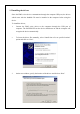
1.2 Installing the drivers Since the EMG series devices communicate through the computer USB port, the drivers which come with the bundled CD must be installed to the computer before using the device. To install the drivers; 1. Connect the EMG series device to the computers through the USB port of computer. The POWER LED on the device should turn on and the computer will recognize the device automatically. 2.
4. Click on “Continue” on the next window 5. The system will copy the necessary files to the computer. 6. Copying progress is finished and the EMG Series device is now ready to use. 7.
2. Configuration 2.1 Main Device Parameters In order for the device to function properly, both the RS-485 serial communication parameters and the network parameters have to be configured correctly. Incorrect or incomplete configuration of these parameters can degrade the system performance and even disrupt the existing network infrastructure. Network Settings Connection Server Setting DHCP Off WEB Access Off Log-in Timeout 120000 ms Link Auto IP Address 192.168.2 240 Gateway Address 192.168.2.
2.1.1 RS485 Serial Communication Parameters EMG Series device uses these parameters along with other units to which the device is serially connected. For high performance communication, all the device parameters over an RS-485 network must be configured the same. 2.1.1.1 Baud Rate Defines the communication speed of the device. Supported rates are: 1200, 2400, 4800, 9600, 19200, 38400, 57600, 115200 bps. 2.1.1.2 Data Bit Defines the data packet size. Supported bit values are: 5, 6, 7, 8. 2.1.1.
2.1.2.2 DHCP If you want the device to obtain the IP address from the DHCP server, activate this option. It is recommended to use this option only when the EMG Series device is operating in client mode. 2.1.2.3 WEB Access If you want the configuration of the device settings from the WEB interface, activate this option. 2.1.2.4 WEB Port You can configure the port which will be used for WEB access from here. 2.1.2.
2.1.2.10 MODBUS/TCP Port Applications which use the TCP/IP protocol while communicating over the internet require a preassigned port number. Some of these port number may already be appointed to other processes. For example, port 80 is reserved for HTTP and port 23 is reserved for TELNET. For MODBUS/TCP protocol, this port number is assigned as 502. It isn't mandatory for the MODBUS/TCP applications to communicate using this port but the software applications must support this port too. 2.1.2.
Some additions to the MODBUS protocol have been made according to the network structure in the MODBUS/TCP protocol. An example of a MODBUS/TCP data packet is given in Figure 2. As you can see, there is an MBAP header in the packet structure. The explanations of the data blocks are given in Figure 2. Figure 2. Modbus Packet Structure Query Number MODBUS protocol is a request/response based protocol. It means that which response belongs to which request is already defined when the first request is created.
In this scenario, let's imagine that the client produced (N-1)th and Nth request packets one after another and sent those to the gateway over the internet. Although the destination IP address of both packets is the same, these packets may follow different paths to their destinations(For example, (N-1)th packet may follow the A-B-C-D path and Nth packet may follow the A-E-D path). As a result, Nth packet may arrive the destination before (N-1)th packet arrives.
2.1.4 Configuration example for communicating over ADSL modem In the example below, an application which shows how you can access your devices which are connected to a remote network using EMG Ethernet-MODBUS Gateway is given. The program in this example runs on a computer with an IP address of 192.168.2.12 and the EMG Series device is placed on the remote network under the sub-net with an IP address of 88.247.188.31.
Select the NAT Menu from the left side of the screen and activate this option. Select Port Forwarding under the NAT Menu and add the EMG Series device to the port forwarding list as shown below. After you save the changes you will be able to monitor the serially connected devices over the internet.
2.1 Reading/Changing the Configuration using the USB interface You can use the EMG Configuration Tool software in the bundled CD to change the settings on the EMG. To do this; 1. Connect your device using the USB port. 2. POWER LED will light up. 3. Run the file EMG Configuration Tool.exe. 4. After the program starts, the settings of the device will show up automatically.
5. After that, you will be able to see the device settings any time you click on the Read button. 6. To change the settings on your device, click on the Update button after you enter the new settings. The new settings will be installed and shown on the program. Not: For the new settings to be in effect, you must power off and on the device. 2.1 Security Settings In this section, you can learn the password which is used to access the device using the WEB interface or change an existing password.
2. Under the Password section, your existing password which is used to access the device using the WEB interface will be shown. 3. To change your password, click on the Change Password box. 4. After you enter your new password in the active text fields and click Update button, your new password will be shown. Not: If you committed any changes on the system settings, all of the changes will be installed with the new password. 2.
2. You will be asked to enter a password to access the System Settings. When the device first starts to operate, the default password is emgxx and it is case sensitive(for EMG12 → ”emg12”, for EMG-10 → “emg10”, for EMG-02 → “emg02”) 3. If you entered the correct password, you will be directed to the settings page. If you enter a wrong password, you will be asked to enter the correct password again(there is no limit).
4. After you made the desired setting changes, click on the UPDATE button. To install the settings that you made, click on the “Save Changes” button. The EMG will reset and your new settings will be activated. 3. Firmware Updates If there are necessary updates or new additions to the EMG firmware, you can install them to the device using the USB port. The latest version of the firmware can be downloaded from http://www.entes.com.tr.
2. Click on the Open button and locate the ROM file you want to insatall. 3. Click on the Update button. After the device is reset, the installation of the new firmware will start. 4. After the firmware update is successful, disconnect the power supply of the device and reconnect it.
4. Appendices Appendix A Differences between EMG model devices EMG10: Allows only 1 TCP connection. EMG12 Allows 4 TCP connections at the same time. EMG02 It is similar to EMG12 but allows request only sent to MODBUS addresses 1 and 2. This model also doesn't support the MODBUS Tunnel Mode. Appendix B Query Interval and TCP Time-Out When querying on the Ethernet/MODBUS Gateway devices using the client software, the query interval must not exceed 1.5 minutes. After 1.