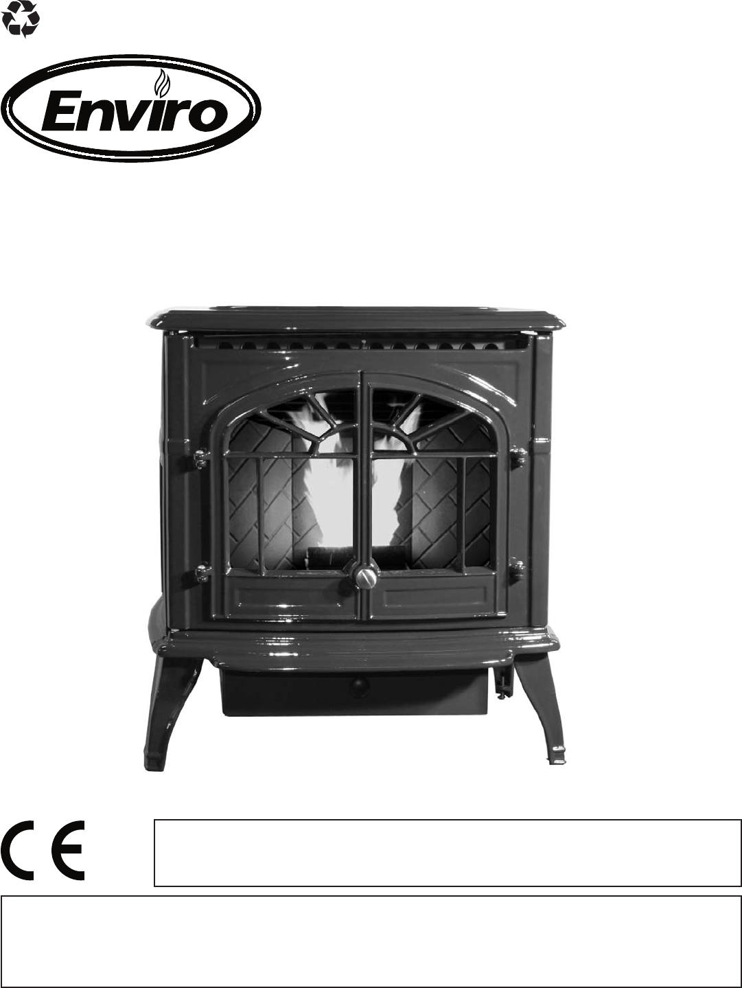
SHERWOOD INDUSTRIES IS AN ENVIRONMENTALLY RESPONSIBLE COMPANY. THIS MANUAL IS PRINTED ON RECYCLED PAPER. PLEASE KEEP THESE INSTRUCTIONS FOR FUTURE REFERENCE PELLET STOVE WINDSOR TECHNICAL MANUAL ���� Contact your building or fire officials about restrictions and installation inspection requirements in your area. PLEASE READ THIS ENTIRE MANUAL BEFORE INSTALLATION AND USE OF THIS PELLET-BURNING ROOM HEATER.
Table of Contents Safety Warnings & Recommendations.........................................................................3 Installation...............................................................................................................6 Rating Label Location.....................................................................................6 Deciding Where to Locate your Pellet Appliance................................................6 Removing Pellet Stove From Pallet........................
Safety Warnings & Recommendations * This manual is designed for the technician in conjunction with the owner’s manual. * Please read this entire Owner’s Manual before installing or operating your ENVIRO Pellet Stove. Failure to follow these instructions may result in property damage, bodily injury or even death. Any unauthorized modification of the appliance or use of replacement parts not recommended by the manufacturer is prohibited.
Safety Warnings & Recommendations CLEANING: There will be some build up of fly ash and small amounts of creosote in the exhaust. This will vary due to the ash content of the fuel used and the operation of the stove. It is advisable to inspect and clean the exhaust vent semi-annually or every two tons of pellets. The appliance, flue gas connector and the chimney flue require regular cleaning. Check them for blockage prior to re-lighting after a prolonged shut down period.
Safety Warnings & Recommendations FRESH AIR: Outside Fresh Air connection is optional. Fresh Air must be connected to all units installed in “Air Tight Homes” or where required by local codes. Consider all large air moving devices when installing your unit and provide room air accordingly. NOTE: Extractor fans when operating in the same room or space as the appliance, may cause problems. Limited air for combustion may result in poor performance, smoking and other side effects of poor combustion.
Installation RATING LABEL LOCATION: The rating label is located on the back of the hopper. DECIDING WHERE TO LOCATE YOUR PELLET APPLIANCE: 1. Check clearances to combustibles (see INSTALLATION - CLEARANCES TO COMBUSTIBLES and INSTALLATION - ALCOVE CLEARANCES). 2. Do not obtain combustion air from an attic, garage or any unventilated space. Combustion air may be obtained from a ventilated crawlspace. 3. Do not install the stove in a bedroom. 4.
Installation DIMENSIONS & SPECIFICATIONS: 141/4" (360mm) 153/8" (390mm) 257/8" (659mm) 253/4" (653mm) 271/8" (689mm) 241/8" (614mm) Figure 2: Windsor Dimensions. Table 1: Windsor Specifications. Classification Testing Standard Description Class I IP-20 EN14785:2006 Residential Wood Pellet Heater Voltage Current Frequency 220 - 240 V 2.0 - 2.3 Amps 50 Hz Maximum Power Requirement Fuel type Calorific value of Pellet used 525W (1793 BTU/hr) wood pellets - 6mm (1⁄4”) dia. ≥ 5.
Installation CLEARANCES TO COMBUSTIBLES: These dimensions are minimum clearances but it is recommended that you ensure sufficient room for serving, routine cleaning and maintenance. 200mm 100mm 100mm 800mm (77⁄8 inches) (4 inches) (4 inches) (311⁄2” inches) This pellet stove requires floor protection. The floor protection must be non-combustible, extending beneath the stove the full width and depth of the unit including 150mm (6“) in front for ember protection.
Installation VENT TERMINATION REQUIREMENTS: IT IS RECOMMENDED THAT YOUR PELLET STOVE BE INSTALLED BY AN AUTHORIZED DEALER/INSTALLER. Table 2: Use in conjunction with Figure 5 for allowable exterior vent termination locations. Letter Minimum Clearance Description A 24 in (61 cm) B 48 in (122 cm) Beside/below any door or window that may be opened. (18” (46 cm) if outside fresh air install.) C 12 in (30 cm) Above any door or window that may be opened. (9” (23 cm) if outside fresh air install.
Installation EXHAUST AND FRESH AIR INTAKE LOCATIONS: 8 3/8” (214 mm) 4 3/8” (112 mm) 12 7/8” (326 mm) INSTALL VENT AT CLEARANCES SPECIFIED BY THE VENTING MANUFACTURER 10 1/2” (265 mm) 8 1/2” (216 mm) Figure 6: Inlet and Outlet Location. EXHAUST Base of unit to center of flue Side of unit to center of flue Center of unit to center of flue 270 mm 308 mm 19 mm (10 5⁄8”) (12 1⁄8”) (3⁄4”) FRESH AIR INTAKE.
Installation CORNER THROUGH WALL INSTALLATION: Fresh Air Intake 100mm (4") Wall thimble manufactured by pellet vent manufacturer. 100mm (4") Figure 8: Corner Installation. HORIZONTAL EXHAUST THROUGH WALL INSTALLATION: Vent installation: install vent at clearances specified by the vent manufacturer. A chimney connector shall not pass through an attic or roof space, closet or similar concealed spaces, or a floor, or ceiling.
Installation 9. Push the stove straight back, leaving a minimum of 100mm (4”) clearance from the back of the stove to the wall. Seal the vent pipe to the thimble with high temperature silicone. Exhaust 80mm (3") or 100mm (4") Vent Pipe 10. The pipe must extend at Wall Thimble least 30 cm (12”) away from the building. If 45o Elbow with Screen necessary, bring another Fresh Air Intake or Termination Cap length of pipe to the outside of the home to connect to the first High Temperature RTV section.
Installation VERTICAL RISE WITH HORIZONTAL TERMINATION INSTALLATION (RECOMMENDED): Termination cap 90°elbow Wall framing A 45° elbow with a rodent screen may be used in place of the termination cap (or stainless steel termination hood). Vertical section of vent pipe Wall strap Horizontal frame for thimble Clean out tee Wall thimble ������ ������� Figure 11: Through Wall with Horizontal Termination.
Installation INSIDE VERTICAL INSTALLATIONS: 1. Choose a stove location that is ideal. See the section “DECIDING WHERE TO LOCATE YOUR PELLET APPLIANCE.” 2. Place a non-combustible hearth pad where necessary. 3. Place the unit on the hearth pad (if installed on a carpeted surface) and space the unit in a manner so when the pellet vent is installed vertically, it will be Rain cap - ensure cap is at 100mm (4”) away from a least 900mm (3 feet) above combustible wall. the roof at the lowest point 4.
Installation OUTSIDE VERTICAL INSTALLATIONS: To accomplish a outside vertical pipe installation, follow steps 1 through 5 in the “INSIDE VERTICAL INSTALLATIONS - FREESTANDING” section and then finish it by performing the following (refer to Figure 14). 1. Install a tee with clean out on the outside of the house. 2. Install vent pipe upward from the tee. Make sure that you install support brackets to keep the vent straight and secure. 3.
Installation HEARTH MOUNT INSTALLATION: Damper Removed or Fastened Open Mantel Minimum 200mm (8") from top of stove Clean-out Fresh-air intake should com from chimney. If holes already exist fresh-air intake can be taken through back of the fireplace or through the ash dump. Min 150mm (6") Floor Protection Masonry Fireplace Combustible Floor Figure 15: Hearth Mount - Side View. Rain cap - ensure cap is at least 900mm (3 ft) above the roof at the lowest point Storm Collar Seal Plate 1.
Installation INSTALLATION WITH EXTERIOR MOUNTED EXHAUST BLOWER: The WINDSOR can be equipped with an externally mounted exhaust blower (PART #50-492). This optional kit will include all components necessary to install the exhaust blower on any external vertical wall surface. Choose a location for your stove that meets the requirements stated in this manual and allows installation with the least amount of interference to house framing, plumbing, wiring, etc.
Installation 9. Connect the wires in the stove. Re-install the left side access cover to the stove and the back grill on the exterior vent housing. 10. Set the Slider Damper as described in the INSTALLATION - SLIDER/DAMPER SETTING“ section. NOTE: Ensure that all vent connections are installed by placing three (3) screws evenly spaced and a small bead of high temperature silicone at each chimney connection.
Installation THROUGH WALL VERTICAL INSTALLATION WITH EXHAUST BLOWER: Refer to INSTALLATION - INSTALLATION WITH EXTERIOR MOUNTED EXHAUST BLOWER and INSTALLATION - OUTSIDE VERTICAL INSTALLATIONS. Ensure that vent pipe is properly secured to wall using wall straps. Maintain clearances to combustibles on vent pipe as well as unit.
Installation THERMOSTAT INSTALLATION: 1. Install the wall thermostat (12 or 24 Volt rated) in a location that is not to close too the unit but will effectively heat the desired area. 2. Connect the Thermostat or Timer using an 2 x 18 gauge wire from the unit to the thermostat. Remove jumper wire and install thermostat wires here. If the unit has been placed in the HI / LOW mode, the unit will be taken to a low or idle setting when the thermostat is not calling for heat.
Installation The slider damper is located behind the left cab side. Undo the two (2) T-20 torx screws that hold the inspection cover on the left side and remove. The combustion exhaust blower is a variable speed blower controlled by the heat output button. This blower will decrease the vacuum pressure inside the stove and as the heat output button is turned down. The vacuum pressure inside the firebox will increase as the combustion exhaust blower increases in speed (higher heat output setting).
Troubleshooting DO NOT: ● Service the stove with wet hands. The stove is an electrical appliance, which may pose a shock hazard if handled improperly. Only qualified technicians should deal with possible internal electrical failures. ● Do not remove from the firebox any screws without penetrating oil lubrication. ● Hold the ON / OFF BUTTON down. This is a momentary contact switch and can be damaged if held down too long. WHAT TO DO IF: 1. The stove will not start. 2. The stove will not operate when hot. 3.
Troubleshooting üCheck vacuum levels in the exhaust channel by bypassing the vacuum switch, then remove the vacuum hose from vacuum switch. Check exhaust vacuum readings by placing the open end of the vacuum hose on a Magnahelic Gauge (readings must be above 0.18” to 0.20” W.C. (44.8 to 49.8 Pa) on low fire). If the motor fails to reach a 0.10” W.C. readings, then replace the combustion blower.
Troubleshooting üIf the auger gear box does not turn but the motor’s armature does try to spin then the auger is jammed. – Try to break apart jam by poking at the jam through the drop tube. If this fails then empty the hopper and remove the auger cover **remember to re-seal the cover after installation** üCheck the fuse on the circuit board. 6. The 200 °F ( 93 °C) high limit temperature sensor has tripped.
Wiring Diagram Armor Cable Supplied Optional Exterior Exhaust Blower Black White Combustion Blower Brown Exhaust Temperature Sensor Brown White Blue Red White Black Black Ground Brown Thermostat 5 Amp Fuse Ignitor Blue 240V Filter White Auger Motor Yellow Ground Red Red Yellow Black White Orange Orange Purple Blue Yellow Red Grey Grey Brown Brown Connect Thermostat Here Vacuum Switch Purple White Orange Orange Convection Blower High Limit Temperature Sensor 25
Parts List - Components Reference Number 1 2 3 120 °F (49 °C) Ceramic Fan Temperature Sensor Auger Motor - 220V High Limit Temp Sensor 200 °F (93 °C) Manual Reset Silicone Hose External Exhaust Back External Exhaust Box External Exhaust Bottom Part Number EC-001 EF-001-220V EF-016 EF-018 EF5-143 EF5-144 EF5-145 4 4 NZ Power Cord - 220V 20-011 IEC Power Cord - 220V 20-013 5 Ignitor - 220V Door Screen Heat Exchanger Rod Cast Brick Panel - Left Cast Brick Panel - Right Cast Brick Panel - Center Brick
Parts List - Components Reference Number 22 23 24 25 26 27 28 29 29 30 31 32 33 34 35 36 37 38 39 40 Description Auger Motor Mount Auger Plate with bushing Auger Mounting Hardware IEC Power Cord Inlet Socket Hinge Pin - Silver Oval Ceramic Gasket Circuit Board 5 Amp Fuses - 220V (Pair) Exhaust Starter Tube 80mm x 21⁄2” Long Combustion/ Exhaust Blower - 220V Door Bolt, Hardened Bushing & Nut Ignition Burn Pot Vacuum Switch - Low Presure Burn Pot Liner with Sides Control Panel with Decal Control Panel Dec
Parts List - Cast Reference Number 41 42 43 44 45 46 28 Description Cast Ash Shelf - Painted Cast Front Complete (Doors & Ash Shelf) - Painted Cast Side Left - Painted Cast Side Right - Painted Cast Grate - Painted Cast Top Only (No Grate) - Painted Complete Cast Body - Painted Complete Cast Body - Antique White Complete Cast Body - Diamond Black Complete Cast Body - Inferno Red Complete Cast Body - Pearl Grey Complete Cast Body - Wedgewood Blue Complete Cast Body - Westport Green Complete Cast Body - Ant
�� �� �� �� �� � �� � �� � � �� �� �� May 2007 WINDSOR - Components Parts Diagram - Components 29
Parts Diagram - Steel & Cast May 2007 �� �� �� �� WINDSOR - Steel & Cast �� �� �� �� �� �� � � �� �� �� �� �� � �� �� � �� �� �� � �� �� �� �� �� �� �� �� �� �� �� 30
Installation Data Sheet The following information must be recorded by the installer for warranty purposes and future reference.