SHERWOOD INDUSTRIES IS AN ENVIRONMENTALLY RESPONSIBLE COMPANY. THIS MANUAL IS PRINTED ON RECYCLED PAPER. PLEASE KEEP THESE INSTRUCTIONS FOR FUTURE REFERENCE PELLET STOVE Evolution TECHNICAL MANUAL ���� PLEASE READ THIS ENTIRE MANUAL BEFORE INSTALLATION AND USE OF THIS PELLET BURNING ROOM HEATER.
Table of Contents Safety Warnings & Recommendations...............................................................................................3 Installation.....................................................................................................................................6 Rating Label Location................................................................................................................6 Deciding Where to Locate your Pellet Appliance....................................
Safety Warnings & Recommendations * This manual is designed for the technician in conjunction with the owner’s manual. * Please read this entire Owner’s Manual before installing or operating your ENVIRO Pellet Stove. Failure to follow these instructions may result in property damage, bodily injury or even death. Any unauthorized modification of the appliance or use of replacement parts not recommended by the manufacturer is prohibited.
Safety Warnings & Recommendations CLEANING: There will be some build up of fly ash and small amounts of creosote in the exhaust. This will vary due to the ash content of the fuel used and the operation of the stove. It is advisable to inspect and clean the exhaust vent semi-annually or every two tons of pellets. The appliance, flue gas connector and the chimney flue require regular cleaning. Check them for blockage prior to re-lighting after a prolonged shut down period.
Safety Warnings & Recommendations FRESH AIR: Outside Fresh Air connection is optional. Fresh Air must be connected to all units installed in “Air Tight Homes” or where required by local codes. Consider all large air moving devices when installing your unit and provide room air accordingly. NOTE: Extractor fans when operating in the same room or space as the appliance, may cause problems. Limited air for combustion may result in poor performance, smoking and other side effects of poor combustion.
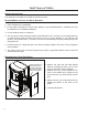
Installation RATING LABEL LOCATION: The rating label is located on the inside of the ash pan cover. DECIDING WHERE TO LOCATE YOUR PELLET APPLIANCE: 1. Check clearances to combustibles. 2. Do not obtain combustion air from an attic, garage or any unventilated space. Combustion air may be obtained from a ventilated crawlspace. 3. Do not install the stove in a bedroom. 4.
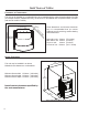
Installation DIMENSIONS: 27 7/8" (708 mm) Unit Dimensions Height: 840 mm (33 1/16”) Width: 565 mm (22 1⁄4”) Depth: 539 mm (21 1⁄4”) Hearth Pad: Width: 619 mm (24 3⁄8”) Depth: 708 mm (27 7⁄8”) IMPORTANT: When not installing the optional Hearth Pad on the unit, the minimum requirements for protection on combustibles floors are a width of 620mm (243⁄8”) & depth of 670mm (263⁄8”) under the unit.
Installation CLEARANCES TO COMBUSTIBLES: This unit can be installed on a combustible floor when installed with the optional hearth pad part 50-1568 (for example linoleum, hardwood flooring). If this unit is to be installed onto a carpeted surface, a hearth pad must be used for stability. Back Wall 4" (10cm) 4" (10cm) Side Wall l al tW n ce ja Ad 77/8" (20cm) These dimensions are minimum clearances but it is recommended that you ensure sufficient room for servicing, routine cleaning and maintenance.
Installation HEARTH PAD PEDESTAL INSTALLATION: This unit can be installed on a combustible floor (e.g. linoleum, hardwood flooring) when the Optional Hearth Pad is installed. If this unit is to be installed onto a carpeted surface, a solid pad must be used underneath the Optional Hearth Pad for stability. Carefully place the the pellet appliance on its back, on the pallet (allow the exhaust tube to fit thru an opening in the pallet).
Installation VENT TERMINATION REQUIREMENTS: IT IS RECOMMENDED THAT YOUR PELLET STOVE BE INSTALLED BY AN AUTHORIZED DEALER/INSTALLER. Table 2: Use in conjunction with Figure 6 for allowable exterior vent termination locations. Letter Minimum Clearance A 61cm (24 in) B C D Description Above grass, top of plants, wood, or any other combustible materials. 122 cm (48 in) Beside/below any door or window that may be opened. (46 cm (18”) if outside fresh air install.
Installation OUTSIDE FRESH-AIR CONNECTION: This Heater must have adequate air for proper combustion in the room that it is installed. A Fresh-air intake is strongly recommended for all installations. Failure to install intake air may result in improper combustion as well as the unit smoking during power failures. ������� ���� The inlet to the intake must be below and a minimum of 305mm (12”) away from the unit exhaust outlet.
Installation MOBILE HOME INSTALLATION: ● Secure the heater to the floor using the two holes in the pedestal. ● Ensure the unit is electrically grounded to the chassis of your home (permanently). ● Do not install in a room people sleep in. ● Outside fresh air is mandatory. Secure outside air connections directly to fresh air intake pipe and secure with three (3) screws evenly spaced. CAUTION: THE STRUCTURAL INTEGRITY OF THE MANUFACTURED HOME FLOOR, WALL AND CEILING/ROOF MUST BE MAINTAINED.
Installation HORIZONTAL EXHAUST THROUGH WALL INSTALLATION: Vent installation: install vent at clearances specified by the vent manufacturer. A chimney connector shall not pass through an attic or roof space, closet or similar concealed spaces, or a floor, or ceiling. Where passage through a wall or partition of combustible construction is desired, the installation must conform with all local regulations, including those referring to regional, national or European Standards.
Installation • Follow vent manufacturer’s guidelines for installation of venting. High temperature sealant must be used when connecting the vent pipe to the unit’s starter pipe. Improper seals at the vent joints may cause combustion byproducts to leak into the room where installed - seal as required..
Installation INSIDE VERTICAL INSTALLATIONS: 1. Choose a stove location that is ideal. See the section “DECIDING WHERE TO LOCATE YOUR PELLET APPLIANCE.” 2. Place a non-combustible hearth pad where necessary. 3. Place the unit on the hearth pad (if installed on a carpeted surface) and space the unit in a manner so when the pellet vent is installed vertically, it will be 100mm (4”) away from a combustible wall. 4. Locate the center of the fresh air intake pipe on the unit.
Installation Rain cap Flashing 24" (61 cm) 4" (10cm) 3" (7.5 cm) Clearance Support bracket Tee with cleanout Type "L" vent Fresh air intake Figure 15: Outside Vertical Installation.
Installation EXTERIOR MOUNTED EXHAUST BLOWER: The Evolution can be equipped with an externally mounted exhaust blower. This optional kit includes all components necessary to install the exhaust blower on any vertical wall surface. Choose a location for your stove that meets the requirements stated in your manual and allows installation with the least amount of interference with house framing, plumbing, wiring, etc. Included in the Exterior Mounted Exhaust Blower Kit are: 1 - Exhaust blower housing box.
Installation TYPICAL THROUGH WALL WITH EXTERIOR BLOWER KIT INSTALLATION - HORIZONTAL TERMINATION: EF 5 90° Elbow 45°Elbow with Rodent screen or stainless steel termination hood 2ft Riser Pipe Adaptor Electrical Cable Exterior Blower and Housing Figure 20: Through Wall Installation with Exterior Blower Kit. NOTE: Ensure that all interior vent connections are sealed by placing a small bead of high temperature silicone around each chimney connection.
Installation TYPICAL THROUGH WALL WITH EXTERIOR BLOWER KIT INSTALLATION - VERTICAL TERMINATION: Follow the previous pages for through wall installations. Ensure that vent pipe is properly secured to wall using wall straps. Maintain clearances to combustibles on vent pipe as well as unit. Roof Sheathing Rain Cap Roof Flashing Roof Rafters Ceiling Joists Vent Pipe Exterior Wall Sheathing Outside Vent Termination EF5 Figure 22: Through Wall Installation with Exterior Blower Kit; Vertical Termination.
Installation THERMOSTAT INSTALLATION: 1. Install the wall thermostat (12 or 24 Volt rated) in a location that is not to close too the unit but will effectively heat the desired area. 2. Connect the Thermostat or Timer using an 2 x 18 gauge wire from the unit to the thermostat. If the unit has been placed in the HI / LOW mode, the unit will be taken to a low or idle setting when the thermostat is not calling for heat.
Installation SLIDER/DAMPER SET-UP: This is used to regulate the airflow through the pellet stove. The slider damper should be set by a trained technician using magnehelic. The slider damper is located behind the left side panel. To open the left side panel, undo the one screw located in the upper front corner of the cabinet side between the louvers. Also loosen three screws down the back of the side panel. The combustion exhaust blower is a variable speed blower controlled by the heat output button.
Troubleshooting DO NOT: ● Service the stove with wet hands. The stove is an electrical appliance, which may pose a shock hazard if handled improperly. Only qualified technicians should deal with possible internal electrical failures. ● Do not remove from the firebox any screws without penetrating oil lubrication. WHAT TO DO IF: 1. The stove will not start. 2. The stove will not operate when hot. 3. The exhaust blower will not function normally. 4. Light # 2 on Heat output bar flashing. 5.
Troubleshooting üPoor Quality Fuel – Insufficient energy in the fuel to produce enough heat to keep the stove burning or operational. üExhaust Temperature Sensor failure. – Bypass sensor located on Exhaust Blower if stove now operates properly, the unit may require cleaning or a new sensor. Contact your local dealer for service. üCheck the fuse on the circuit board. 3. The exhaust motor will not function normally. üOpen the left side access panel; check all connections against the wiring diagram. üSee “2.
Troubleshooting 7. The convection blower will not function normally. üClean all grill openings at the back and below unit . üPress the fan button; does the fan come on? Press again to verify that the blower turns on; if, not contact your local dealer for service. 8. Ignitor- the pellets will not light. üEverything else in the stove operates but the ignitor will not light the pellets.
Wiring Diagram Armor Cable Supplied Optional Exterior Exhaust Blower Grey Grey Black Combustion Blower Vacuum Switch White White Blue Brown Exhaust Temperature Sensor Power Cord Brown Ground Thermostat 5 Amp Fuse Black White Orange Orange Purple Blue Yellow Red Grey Grey Brown Brown Red Red 115V White 220V Blue 115V Black 220V Brown Connect Thermostat Here Hot Red White Black Black Common Ignitor Purple White Yellow White Orange Orange Convection Blower Auger Motor High Limit Tempera
Parts List Reference # 1 2 Part # 120°F (49°C) Ceramic Fan Temperature Sensor EC-001 Window Channel Tape - 1.
Parts List Reference # Description Part # Door Gasket - 7ft (213 m) 50-088 23 Top Louver Set - Nickel 50-097 24 Ash Shelf Louver 50-162 Slider Damper Rod & Knob 50-293 Top Glass Retainer 50-294 Control Panel Touch Latch 50-323 Circuit Board Wire Harness 50-332 Hopper Guard 50-333 25 Convection Blower - 220V 50-513 26 Convection Blower Mount & Hardware 50-585 27 External Exhaust Kit (80mm Pipe) 50-492 28 400 Watt Ignitor - 220V 50-646 Auger Mounting Hardware 50-689 IEC Powe
Parts Diagram - Components �� � �� � �� �� � �� �� � �� �� �� �� EVOLUTION - Components May 2007 28 ��
�� �� �� �� �� May 2007 EVOLUTION - Steel Components �� �� �� �� �� �� �� � �� � �� � �� �� �� �� �� �� �� � �� � �� �� Parts Diagram - Steel 29
Installation Data Sheet The following information must be recorded by the installer for warranty purposes and future reference.