SHERWOOD INDUSTRIES IS AN ENVIRONMENTALLY RESPONSIBLE COMPANY THIS MANUAL IS PRINTED ON RECYCLED PAPER 8 2 8 By SHERWOOD INDUSTRIES LTD. Direct Vent O W N E R S M A N U A L Installation And Operating Instructions For Models: 828 MH (MOBILE HOME) 828 DV. FS. (Freestanding) 828 DV. INS. (Insert) WARNING WHAT TO DO IF YOU SMELL GAS • Open windows/Extinguish any open flame • Do not try to light any appliance. • Do not touch any electrical switch; do not use any phone in your building.
SAFETY PRECAUTIONS FOR SAFE INSTALLATION AND OPERATION OF YOUR "ENVIROGAS" ROOM HEATER, PLEASE, CAREFULLY READ THE FOLLOWING INFORMATION: • All "ENVIROGAS" gas-fired appliances must be installed in accordance with these instructions. Carefully read all the instructions in this manual first. Consult the building authority having jurisdiction to determine the need for a permit prior to commencing the installation.
TABLE OF CONTENTS 1 Code Approvals ...........................................................................................................................................3 Specifications...............................................................................................................................................3 2 Dimensions and Clearances to Combustibles .............................................................................................4 Zero Clearance Box Assembly ..........
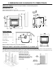
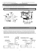
2. DIMENSIONS AND CLEARANCES TO COMBUSTIBLES FIREPLACE INSERT: The stove can only be installed in a solid fuel burning fireplace .
ZERO CLEARANCE BOX ASSEMBLY; First take the kit from the box and place the surround panels aside so as not to damage the panels. There will also be a bag of screws, nuts and bolts in the box. The bottom section of the kit will have two 3 inch square boxes mounted to the bottom. First attach the bottom to the back with the screws provided, the hole should be located in the lower right hand corner looking at it from the front. The side can then be mounted to the bottom panel and the back panel.
3. DECIDING WHERE TO LOCATE YOUR STOVE FREESTANDING: • Locate the stove in a large and open room that is centrally located in the house. This will optimize heat circulation and comfort. • The stove should be located out of traffic, away from furniture and draperies and should have sufficient access for its safe operation and maintenance.
FIREPLACE INSERT • Carefully clean the fireplace and flue before installing the stove. Failure to do so may result in fumes or dirt being blown into the room or insert and may cause a fire leading to death or serious injury. • If you are installing the optional fan kit, (see Installing Fan Kit) do so now. • If the fireplace has a dropped or uneven bottom, install the optional rear leveling legs. The leg brackets attach into the side rear of the firebox with the torx screws provided.
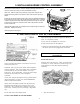
5. INSTALLING BURNER CONTROL ASSEMBLY Remove the controls from box, check for shipping damage. Remove burner tray from controls (one screw on each side between burners). Open door. Remove grate rod by pulling up at each end. Remove the 2 screws behind the grate and one screw on each side of control opening in firebox. Extend flex gas line and place through hole in center of pedestal (freestanding and inserts) or through hole in right or left firebox side (insert only).
2. Place the log with Burnt Area forward on log supports. Locate the log by matching the bottom 3. pegs to the receiving holes in rear log supports. Close door securely 7. ELECTRICAL REQUIREMENTS The ENVIROGAS 828 Series will operate without an external electrical power supply. This model has a Millivolt gas control which uses the pilot flame to generate enough electricity to operate the main burners. CAUTION: Label all wires prior to disconnection when servicing controls.
8. GAS LINE CONNECTION AND TESTING WARNING: Only persons licensed to work with gas piping can make the gas connections to this appliance. This appliance is equipped with a 3/8” stainless steel flex line from the valve. This line may be routed through the hole in the rear of the pedestal, or on inserts, routed through the fire box sides. An adapter plate is available for installations that do not allow flex pipe through cabinetry. NOTE: Consult your local authorities and in CAN.
9. AIR SHUTTER ADJUSTMENT • • • There is a separate venturi air shutter for each burner The venturies have been set for installation at sea level to 4,500 ft. To adjust for higher altitudes: Remove the access cover plate, loosen the air shutter locking screws with a long screwdriver. Rotate the air shutters to the correct setting. The flame should be bright yellow in color and have a lively appearance. If sooting occurs on the glass then the venturi opening may need to be increased.
10.
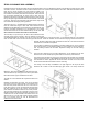
These models have been tested and certified for use with SIMPSON DURAVENT DIRECT VENT TYPE "GS" PIPE FOR GAS STOVE. Kits are available for vertical venting or horizontal venting. It is recommended that a bead of RTV High Temperature Silicone be applied to each vent joint before installation. A MINIMUM VERTICAL LENGTH OF 24" TO THE FIRST 90 DEGREE ELBOW IS REQUIRED. WITH THIS MINIMUM VERTICAL RISE, HORIZONTAL RUNS OF FROM ONE TO FOUR FEET ARE PERMITTED TO REACH THE OUTSIDE VENT TERMINATION.
When planning your installation, it will be necessary to select the proper length of vent pipe for your particular requirements. It is important to note when passing through a wall, the maximum allowable wall thickness is 10-inches (254mm), 1 ½ inches clearance to combustibles must be maintained. Select the amount of vertical rise desired for “vertical-to-horizontal” type installations.
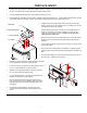
STEP 7. Slide the decorative wall thimble up to the wall surface and attach with the screws provided. Apply decorative brass or chrome trim if desired. FIG-14. FIG. 11 FIG. 12 FIG-13 FIG-14 NOTES: (1) The four wood screws provided should be replaced with the appropriate fasteners for stucco, brick, concrete, or other types of siding. (2) For buildings with vinyl siding, a vinyl siding standoff (950), should be installed between the vent cap and the exterior wall FIG-12.
VERTICAL INSTALLATION STEP 1. Check the instructions for required clearances (air spaces) to combustibles when passing through ceilings, walls, roofs, enclosures, attic rafters , or other nearby combustible surfaces. Do not pack air spaces with insulation. STEP 2. Set the gas appliance in the desired location. Drop a plumb bob down from the ceiling to the position of the appliance flue exit, and mark the location where the vent will penetrate the ceiling. Drill a small hole at this point.
NOTES: (1) If an offset is necessary in the attic to avoid obstructions, it is important to support the vent pipe every 3 feet, to avoid excessive stress on the elbows, and possible separation. Wall straps are available for this purpose. FIG18 (2) When ever possible, use 45° degree elbows instead of 90° degree elbows. The 45° degree elbow offers less restriction to the flow of flue gases and intake air. NOTES: (1) For multi story installations.
CATHEDRAL CEILING INSTALLATION Step 1. Follow installation steps 1 and 2 under Vertical Termination. Step 2. Using the plumb bob, mark the centerline of the venting system on the ceiling and drill a small hole through the ceiling and roof at this point. From the roof, locate the drill hole and mark the outline of the Cathedral Ceiling Support Box. Step 3. Remove shingles or other roof covering as necessary to cut the rectangular hole for the Support Box. Cut the hole 1/8 larger than the support Box outline.
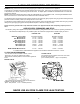
11. MOBILE HOME FUEL CONVERSION To convert from Propane to Natural Gas or vise-versa 1. 2. 3. 4. 5. 6. 7. 8. 9. 10. 11. 12. 13. • • • Disconnect the unit from the gas supply. Open the door and remove the logset. Remove the burner tray (2 screws) and the burner control assembly by removing the 8 screws holding it into the unit. Remove the control panel from the control assembly Undo the pilot tube and thermocouple from the valve. Remove the pilot assembly.
12. OPERATING INSTRUCTIONS FOR YOUR SAFETY READ BEFORE OPERATING WARNING: IF YOU DO NOT FOLLOW THESE INSTRUCTIONS EXACTLY, A FIRE OR EXPLOSION MAY RESULT CAUSING PROPERTY DAMAGE, PERSONAL INJURY OR LOSS OF LIFE. A) This appliance is equipped with a pilot that must be lit by hand by following these instructions exactly. B) BEFORE LIGHTING smell all around the appliance area for gas, and next to the floor because some gas is heavier than air and will settle on the floor.
13. MAINTENANCE AND TECHNICAL Periodically check to ensure that your "Direct Vent" system is clear. Periodically check the pilot and burner. Check to see that all the burner ports are clean and clear. Check the pilot head for blockage. Check to ensure the pilot flame is blue with small yellow tips. OPENING THE DOOR Caution door is hot when in operation. To Replace: • open door fully • Lift door vertically so that hinge pins lift out of hinge receivers. • Return the door assembly to dealer.
14.
15. PARTS AND ACCESSORIES Service Parts available from your local Envirogas Dealer.
16. WARRANTY Sherwood Industries Ltd. offers a *Lifetime Warranty on this gas product. The lifetime warranty covers the appliance for a period of seven years from the date of installation. This warranty applies only to the original owner in the original location Covered under the lifetime warranty are Cabinet Sides, Tops, Pedestals, Surround Panels and Chassis and Heat Exchanger.
17. INSTALLATION DATA SHEET The installer for warranty purposes and future reference must record the following information. Envirogas Models: 828.DV. FS. (Freestanding) Direct Vent Room Heater 828 DV. INS. (Insert) 828 DV. MH.