IS U TY N LI N IO ON A R AT SY R A TR A W IS D E .com EG N ro R K A e nv i C Q I N E: Boston Model: 1200-C & 1700C Free Standing OWNERS MANUAL SHERWOOD INDUSTRIES IS AN ENVIRONMENTALLY RESPONSIBLE COMPANY. THIS MANUAL IS PRINTED ON RECYCLED PAPER. PLEASE SAVE THESE INSTRUCTIONS FOR FUTURE REFERENCE INSTALLER: Leave this manual with the wood stove. CONSUMER: Retain this manual for future reference.
Table of Contents Safety Precautions.............................................................................................3 Operating Instructions........................................................................................4 Building Your Fire...................................................................................6 Air Control.............................................................................................9 How It Works................................................
Safety Precautions FOR SAFE INSTALLATION AND OPERATION OF YOUR “ENVIRO” WOOD STOVE, PLEASE CAREFULLY READ THE FOLLOWING INFORMATION: ● Please read this entire manual before you install and use your new woodstove. Failure to follow instructions may result in property damage, bodily injury or even death. Be aware that local Codes and Regulations may override some items in this manual. Check with your local inspector.
Operating Instructions FIRST START When first installed, the chimney, firebricks and steel are cold and it usually takes several hours on a fairly high burn for them to become hot and dry enough for the stove to function well. We recommend during the unit’s first burn that a door and window are opened to vent the smoke and fumes created from the unit’s paint curing. The paint will smell a little for the first burn or two as it cures.
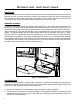
Operating Instructions REPLACING THE GLASS: Never strike or slam the door, hit the glass or let burning wood rest against it. If the glass cracks when the fire is burning, do not open the door until the fire is out and do not operate the stove again until the glass has been replaced. If the glass is damaged in any way, a factory replacement is required (see “Parts List”). To replace the glass, remove the steel retaining clips and all loose glass. Replace only with Neoceram 5 mm glass 16.61” (422 mm) x 10.
Operating Instructions Building Your Fire: Proper operation of your stove will help to ensure safe, efficient heating. Please take a few moments to review these simple operating procedures. IMPORTANT: Please be aware when loading your stove that the air tubes in the rear are lower. 1. Fuel Selection: This stove is designed to burn natural wood only.
Operating Instructions 4. For Maximum Efficiency: When the stove is hot, load it fully to the top of the door opening and burn at medium low settings. When the fuel is mostly consumed, leaving a bed of red coals, repeat the process. Maximum heat for minimum fuel occurs when the stove top temperature is between 250°F (120°C) and 550°F (290°C).
Operating Instructions spillage when refueling, open the door slowly. 3. What does dry, seasoned wood mean? Wood that has been dried for a period of one year in a well-ventilated and sheltered area would be considered dry, seasoned wood. Wood from slow-growing trees is generally considered better than wood from fast-growing trees. To season firewood, split and stack it so that air can get to all parts of the wood. 4.
Operating Instructions drafting. Increased amounts of insulation, vinyl windows, extra caulking in various places and door seals can all keep heat in but may also make a home too airtight. An easy way to stop negative pressure in a home is to crack a window in the room containing the stove. b) Environmental Conditions - High trees, low-lying house location such as in a valley, tall buildings or structures surrounding your house and windy conditions can cause poor draft or down-drafting.
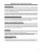
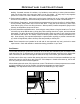
Operating Instructions How It Works: Figure 3: 1200 Air Flow Path.
Specifications 1200 Specifications: Model 1200 Freestanding Width x Depth 30” x 25” (762 mm x 635 mm) Height with legs Fire box size (depth x width x height) Capacity * Approximate heating area 31.75” (806mm) 16.1” x 18.25” x 11.15” (409 mm x 464 mm x 283 mm) 1.85 feet3 (0.0526 meter3) 2200 feet2 (205 meter2) **E.P.A. output rating 11,479 to 34,196 BTU/hour (3,361 to 10,013 watt) *Duration on low burn 6 -10 hours Weight with packaging 335 lb (151.95 Kg) E.P.A.
Specifications 1700 Specifications: Model 1700 Freestanding Width x Depth 30” x 29” (762 mm x 736 mm) Height with legs Fire box size (depth x width x height) Capacity * Approximate heating area 31.75” (806mm) 20.65” x 18.25” x 11.95” (525 mm x 464 mm x 304 mm) 2.5 feet3 (0.0708 meter3) 3000 feet2 (280 meter2) **E.P.A. output rating 9,425 to 31,780 BTU/hour (2,760 to 9,306 watt) *Duration on low burn 8 - 12 hours Weight with packaging 420 lb (190.51 Kg) E.P.A. Emissions Rating Label Location 4.
Specifications Clearances To Combustibles - 1200 Freestanding: MAINTAIN THESE MINIMUM CLEARANCES TO UNSHIELDED COMBUSTIBLES* Adjacent wall A D Front H C Alcove Back wall H Front F G Hearth Alcove Side wall E H C Fr on t Side wall B Adjacent wall Back wall N K O J L M Front I Alcove Table 2: 1200 Freestanding Clearance to Combustibles. Single Wall Pipe Double Wall Pipe** Top vent out back wall with min.
Specifications Clearances To Combustibles - 1700 Freestanding: MAINTAIN THESE MINIMUM CLEARANCES TO UNSHIELDED COMBUSTIBLES* Adjacent wall A D Front H C H C Alcove Back wall H Front F G Hearth Alcove Side wall E Fr on t Side wall B Adjacent wall Back wall N K O J L M Front I Alcove Table 10: 1700 Freestanding Clearance to Combustibles. Single Wall Pipe Double Wall Pipe** Top vent out back wall with min.
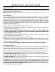
Specifications Dimensions - 1200 Freestanding: 25.00" (635mm) 22.25" (565mm) 5.50" (140mm) 30.00" (762mm) 10.00" (254mm) 16.00" (406mm) 31.75" 30.50" (806mm) (775mm) 17.00" (432mm) 29.125" (740mm) Figure 4: 1200 Freestanding Dimensions. UNLESS OTHERWISE SPECIFIED MATERIAL ALL DIMENSIONS IN INCHES TOLERANCE General Hole Size Hole Pos. Angles +/- .005 +/- .001 +/- .002 +/- .
Specifications Dimensions - 1700 Freestanding: 29.00" (737.00 mm) 26.00" (660 mm) 30.00" (762 mm) 4.75" (121 mm) 10.00" (254 mm) 16.00" (406 mm) 30.5" (775 mm) 17.00" (432 mm) 29.125" (740 mm) Figure 4b: 1700 Freestanding Step Top Dimensions.
Installation Removal From Pallet: • Remove the screws which are securing the shipping brackets to the unit. • Remove the lag bolts and discard the brackets. Figure 5: Bolts to remove.
Installation Hearth Protection Examples: Table 11: Examples of Hearth Pad Sizing Using Clearances From Tables 9 &10 (refer to Figures 22 & 23).
Installation H D USA 6" (152mm) CND 8" (203mm) F USA 6" (152mm) CND 8" (203mm) B J Door Opening USA 16" (406mm) CND 18" (457mm) E C G A I Figure 6: General Parallel Installation (refer to Tables 11 & 12). Optional Coverage O N L USA 6" (152mm) CND 8" (203mm) P K USA 6" (152mm) CND 8" (203mm) Optional Coverage M B Door Opening USA 16" (406mm) CND 18" (457mm) G A Optional Coverage E C Figure 7: General Corner Installation (refer to Tables 11 & 13).
Double Wall Pipe Single Wall Pipe USA 1700 Canada USA 1200 Canada USA 1700 Canada USA 1200 Canada (K) Front of Hearth Pad to Corner 61⅜” (1558mm) 59⅜” (1507mm) 67¼” (1708mm) 65¼” (1657mm) 59⅞” (1522mm) 57⅞” (1471mm) 65⅛” (1654mm) 63⅛” (1603mm) 57⅝” (1465mm) 54⅞” (1393mm) 61⅞” (1571mm) 59” (1499mm) 56⅝” (1439mm) 53⅞” (1368mm) 60⅜” (1533mm) 57½” (1461mm) (L) Adjacent Wall (M) Edge of Hearth Pad to Adjacent Wall 29⅛” (738mm) 29⅛” (738mm) 33¼” (844mm) 33¼” (844mm) 28⅛” (713mm) 28⅛” (713mm) 31¾”
Installation Outside Air Kit: It is mandatory to use outside air for installations in mobile homes. A 4” (10.2 cm) fresh air adaptor kit is available. This kit can be installed on the back of the Ash Box. If outside air is to be used in conjunction with the convection fan kit, there is a separate outside air adapter which connects to the bottom of the Ash Box. Refer to the Parts List. Rear of Ash Box Place the ¼” mesh screen behind the fresh air adaptor (as shown to right).
Installation Chimney Installation Through Wall: Here are four (4) methods of combustible wall chimney connector pass-throughs. Information was provided from NFPA 211. Minimum chimney clearance to brick and combustibles 2 inches (50.8 mm) Chimney Flue Minimum clearance 12 inches (304.8 mm) of brick Chimney connector Fire clay liner Minimum 12 inches (304.8 mm) to combustibles Masonry chimney Figure 9: Chimney Through Wall - Method A.
Installation Installation of A Listed, Factory Built Chimney: This is a generic set of instructions; always follow the chimney manufacturer’s instructions explicitly. Also refer to “Recommended Heights For Flue Pipe”. 1. 2. 3. 4. 5. 6. 7. 8. 9. Set non combustible floor protector and stove in location in accordance with the “Clearances To Combustibles”. Mark the position for the ceiling hole by 2 ft (0.
Installation roof ridge, the chimney must Rain cap/ be 2 feet (60.9 cm) above the Spark arrestor cap ridge. Refer to Figure 13. Storm Collar Note: Increasing the chimney Roof radiation Roof flashing shield (if required) height above the roof may help your unit to draft better. Roof This greater draft can decrease Insulated chimney problems such as difficult start-ups, smoke coming out when door is open, and dirty Minimum Ceiling Minimum air space glass.
Installation Masonry Chimney Installation: DO NOT CONNECT THIS UNIT TO A CHIMNEY FLUE SERVING ANOTHER APPLIANCE. A non-combustible floor protector is required under all freestanding units; refer to “Clearances To Combustibles”. When venting into a masonry chimney, the floor protector must be installed directly below the chimney vent and 2” (50.8 mm) on either side of the chimney vent.
Installation Masonry Fireplace Installation - Freestanding: Rain Cap Steel Plate or Flashing Chimney Support and Clamp Unless you are experienced, we recommend installation by your dealer or a professional installer. Many venting manufacturers have listed kits available to connect a stove to a masonry fireplace. Always follow the vent manufacturer’s installation instructions. Rigid Stainless Steel Liner The existing damper may have to be removed to allow installation.
Installation Chimney must be removable to allow for transportation of the mobile home. Spark arrestor cap CAUTION: THE STRUCTURAL INTEGRITY OF THE MOBILE HOME FLOOR, WALL, AND CEILING/ROOF MUST BE MAINTAINED. OUTSIDE AIR : Connection from the stoves air intake to the outside is mandatory, (MOBILE HOMES ONLY) either through a hole in the wall not higher than the stoves bottom or through a hole in the floor, using the fresh air adaptor.
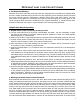
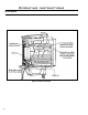
Installation Model 1200 Brick Placement & Tube Locations: COMPLETE THE STOVE AND SMOKE PIPE INSTALLATION BEFORE PLACING THESE BRICKS. Tube E Tube D Tube A ick Br l a e rti S iz l Pa l Fu rick B lf Ha rick B 1. Place the three (3) full size bricks along each side of the firebox and one (1) full size brick on either side of the back of the firebox. 2. To place the floor bricks, lay the two (2) partial bricks along the back of the floor.
Installation Model 1700 Brick Placement & Tube Locations: COMPLETE THE STOVE AND SMOKE PIPE INSTALLATION BEFORE PLACING THESE BRICKS. Tube C Tube B Tube A ick al Br Parti rick ize B Ful l S Half ck Bri 1. Place the four (4) full size bricks along each side of the firebox and one (1) full size brick on either side of the back of the firebox. 2. To place the floor bricks, lay the two (2) partial bricks along the back of the floor.
Installation C-Cast Ceramic Baffle Installation: 1. Slide the right C-Cast Ceramic Baffle in over the secondary air tubes at the top of the firebox. The tab must be on the top and pointing towards the center and the smooth side is to face down. 2. Hook the outside edge of the baffle over the top of the secondary air chamber. This will make room to for the installation of the left C-Cast Ceramic Baffle. Right Ceramic Baffle Left Ceramic Baffle 3.
Installation Fan Black Black White Black White Fan controller Fan temperature sensor Power Supply Figure 22: Freestanding Fan Kit Wiring Diagram. Optional Fan Installation - Freestanding: Refer to Fan Wiring Diagram before installing your optional fan kit. 1. Remove the fan assembly from the box and inspect for any damage to the assembly. If damage is noticed call your dealer, distributor or courier company and have components replaced before installing kit. 2.
DISASSEMBLY Removal of Cast Sides and Door: To remove the cast sides, lift off the Cast Top and then unscrew the slider knob and then remove the two top bolts using a 3/8” socket. The Cast Side may then be lifted up. The door may be taken off by first lifting off the Cast Top and then removing the two bolts from the top door hinge, using a 3/8” socket.
Rating Label DO NOT REMOVE THIS LABEL / NE PAS ENLEVER CETTE ÉTIQUETTE Tested & Listed By Serial No. / No. De Serié: LISTED SOLID FUEL SPACE HEATER / IDENTIFIE COMME UN FOYER A COMBUSTIBLE SOLIDE Certified for use in Canada & USA / Certifié pour installation au Canada et aux Etats-Unis. Model / Modèle: Report/Rapport no.
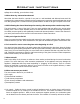
Parts List Reference # 34 Description Part # 1 120°F (49°C) Ceramic Fan Temperature Sensor EC-001 2 Convection Blower 50-2493 3 FPI Fan Controller - 115V EC-039 3 Fan Controller Knob EC-040 4 Domestic power cord - 115V EC-042 5 Boston 1200 FS Fan Kit 50-2417 - Boston 1700 FS Fan Kit 50-2572 6 Fresh Air Kit (for fan) 50-2440 7 Fresh Air Kit EF-186 8 1200 Boston FS Cast Top 50-2441 9 1700 Boston FS Cast Top 50-2582 10 Boston Cast Side Right 50-2443 11 Cast Leg Lip Righ
6 14 2 7 15 1 8 5 16 12 4 3 19 18 20 21 17 9 24 10 25 36 26 27 11 13 29 23 22 30 21 22 28 31 32 33 34 35 Parts Diagram - Freestanding 35
Warranty for Enviro Wood Products Sherwood Industries Ltd. (“Sherwood”) hereby warrants, subject to the terms and conditions herein set forth, this product against defects in material and workmanship during the specified warranty period starting from the date of original purchase at retail. In the event of a defect of material or workmanship during the specified warranty period, Sherwood reserves the right to make repairs or to assess the replacement of a defective product at Sherwood’s factory.
Installation Data Sheet The following information must be recorded by the installer for warranty purposes and future reference.