PLEASE SAVE THESE INSTRUCTIONS FOR FUTURE REFERENCE I AT TR IS EG m R .co o TY vir N A en R R A W SHERWOOD INDUSTRIES IS AN ENVIRONMENTALLY RESPONSIBLE COMPANY. THIS MANUAL IS PRINTED ON RECYCLED PAPER. OWNERS MANUAL INSTALLER: Leave this manual with the wood stove. CONSUMER: Retain this manual for future reference. Contact your local building or fire officials, or the authority having jurisdiction about restrictions and installation inspection requirements in your area.
Table of Contents Safety Precautions..........................................................................................3 Operating Instructions.....................................................................................4 Building Your Fire.................................................................................5 How It Works......................................................................................9 Specifications............................................................
Safety Precautions FOR SAFE INSTALLATION AND OPERATION OF YOUR “ENVIRO” WOOD STOVE, PLEASE CAREFULLY READ THE FOLLOWING INFORMATION: ● Please read this entire manual before you install and use your new woodstove. Failure to follow instructions may result in property damage, bodily injury or even death. Be aware that local Codes and Regulations may override some items in this manual. Check with your local inspector.
Operating Instructions FIRST START When first installed, the chimney, firebricks and steel are cold and it usually takes several hours on a fairly high burn for them to become hot and dry enough for the stove to function well. We recommend during the unit’s first burn that a door and window are opened to vent the smoke and fumes created from the unit’s paint curing. The paint will smell a little for the first burn or two as it cures.
Operating Instructions CREOSOTE - ITS FORMATION AND NEED FOR REMOVAL: When wood is burned slowly, it may produce tar and other organic vapors, which combine with expelled moisture to form creosote. The creosote vapors condense in the relatively cool chimney of a slow-burning fire. As a result, creosote residue accumulates on the flue lining. When ignited this creosote makes an extremely hot fire.
Operating Instructions NOTE: Until the fire is burning well, leave the air controls fully open. d) Regulate the heat output of the stove by adjusting the air controls to allow a larger fire and vice versa. A short period of experimentation with the control settings will allow you to regulate the heat output to keep your home comfortable. Do not use a grate or elevate the fire. Build wood fire on the stove firebox hearth floor. 3.
Operating Instructions some additional kindling may be needed to sustain the fire. DO NOT add more paper after the fire has started. g) Once the kindling has started to burn, add some smaller pieces of seasoned, dry firewood. Note: Adding large pieces at the early stages will only serve to smother the fire. Continue adding small pieces of seasoned dry firewood, keeping the door slightly open until each piece starts to ignite. Remember to always open the door slowly between placing wood into the fire.
Operating Instructions clean, but if you must clean the glass, use a soft cloth with no abrasive and clean only when the unit is cold. Cold firebox temperature and poor draft cause sooting of the glass. Once the firebox temperature and the draft increase, the soot will burn off. Do not use abrasive cleaners on glass. 7. What is draft? Draft is the ability of the chimney to exhaust or draw smoke produced during the normal combustion process.
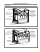
Operating Instructions How It Works: Exhaust Smoke Convection Heat 1/2" Ceramic baffle; reflects heat down to burn the particles in the smoke. Primary air; window air wash (cooler air to keep the glass clean). Secondary air tubes; creates a second burn on the particles in the smoke for a more efficient & cleaner burn. Radiant Heat Pilot air through Twin pilot injection ports. Intake air. Slider plate; used for air flow control. Figure 1: 1200-C Air Flow Path.
Specifications Air Control: The primary air is controlled by the rod located on the right side of the unit. To increase your air, pull the rod out and to decrease, push the rod in. All the units have a secondary air that flows through the tubes at the top of the firebox, just below the baffles. Pull this control all the way out when first starting the stove. Once the fire has been established you may adjust this control to set the burn rate of the fire. For optimal efficiency, use a low to medium setting.
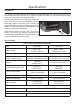
Specifications Clearances To Combustibles - 1200-C Insert: A Minimum clearance to an unshielded side wall 10” (254 mm) B Minimum clearance to an unshielded 8” (203 mm) mantel 21” (533 mm) C Minimum top facing (protruding ¾” [19 mm]) clearance 17½” (445 mm) D Minimum side facing (protruding ¾” [19 mm]) clearance 1” (25 mm) Adjacent wall Table 2: 1200-C Insert Clearance to Combustibles.
Specifications Clearances To Combustibles - 1700-C Insert: A Minimum clearance to an unshielded side wall 10” (254 mm) B Minimum clearance to an unshielded 8” (203 mm) mantel 24” (610 mm) C Minimum top facing (protruding ¾” mm]) clearance [19 D Minimum side facing (protruding ¾” mm]) clearance [19 19½” (495 mm) 1” (25 mm) E † From front of door opening to edge of floor protection USA 16” (406 mm) CND 18” (450 mm) F † From side/back of unit to edge of floor protection USA 6” (152 mm) CND 8”
1 49 8 " (1248mm) 1 35 16 " (891mm) 22 5/16" (566mm) (783mm) Figure 4: 1200-C Insert Dimensions.
Specifications Dimensions - 1700-C Insert: 22 5/16" (566mm) 35 1/16" (891mm) 49 1/8" (1248mm) 20 13/16" (528mm) 30 13/16" (783mm) Figure 5: 1700-C Insert Dimensions.
Installation Failure to follow these instructions carefully could cause personal injury or property damage. Removal From Pallet: • Remove the bricks from the unit before starting. • Remove the two lag bolts (shown in Figure 6) that secure the unit to the pallet from inside the firebox. • Remove the shipping bracket at the rear of the unit. Note: Before the bricks are installed, rivets (Figure 2) must be placed in the two (2) holes (shown in Figure 7) in the firebox that lag bolts came out of.
Installation Masonry Fireplace Installation: Unless you are experienced, we recommend installation by your dealer or a professional installer. Install only in a masonry fireplace with a good-condition chimney at least 15 ft (4.6 m) high, both of which have been constructed in accordance with the building code. Refer to Tables 4 and 7 for minimum masonry fireplace dimensions. Be sure the fireplace and chimney are clean and sound without any cracks or loose mortar.
Installation The flue collar is removable for installations into fireplaces with low openings. USA 16” (406 mm) CND 18” (450 mm) 8" (203 mm) Floor Protection Masonry Fireplace Combustible Floor Figure 11: Insert Installation into existing fireplace without hearth. a) Remove the rear two (2) secondary air tube and C-Cast Ceramic Baffles, if installed (see C-Cast Ceramic Baffle Installation).
Installation Figure 14: Removable flue collar in place. 4. Screw or nail the provided metal plate with the wording “THIS FIREPLACE HAS BEEN ALTERED TO ACCOMMODATE A FIREPLACE INSERT AND SHOULD BE INSPECTED BY A QUALIFIED PERSON PRIOR TO THE RE-USE AS A CONVENTIONAL FIREPLACE.” to the inside of the fireplace. Leveling Legs Figure 15: Leveling legs.
Installation Installation Using A Block-Off Plate For USA Only: If this unit is to be installed into a masonry fireplace or a zero-clearance fireplace with a direct connection you must install a non-combustible seal-off device such as a block-off plate or damper adapter. By installing a block-off plate you seal the chimney, ensuring that no smoke enters the home and sealing the chimney to encourage draft. To construct a block-off plate follow the below steps.
Installation 4. Using the template make the blockoff plate of 24 gauge or thicker steel. Drill two (2) holes in each flange for mounting the plate. 5. Mount the block-off plate using masonry screws in a masonry fireplace and sheet metal screws on a zero-clearance fireplace (screws need only be long enough to penetrate the first layer of metal). 6. Insulate the block-off plate using high - temperature fiberglass insulation and furnace cement. 7.
Installation Model 1200-C Brick Placement & Tube Locations: COMPLETE THE STOVE AND SMOKE PIPE INSTALLATION BEFORE PLACING THESE BRICKS. Tube E Tube D Tube A ick Br l a e rti Pa S iz l l Fu rick B e S iz l l Fu rick B 1. Place the three (3) full size bricks along each side of the firebox and one (1) full size brick on either side of the back of the firebox. 2. To place the floor bricks, lay the two (2) partial bricks along the back of the floor. Then lay four (4) full size bricks in the front.
Installation Model 1700-C Brick Placement & Tube Locations: COMPLETE THE STOVE AND SMOKE PIPE INSTALLATION BEFORE PLACING THESE BRICKS. Tube C Tube B Tube A ick al Br Parti rick ize B Ful l S rick ize B Ful l S rick ize B S l l u F 1. Place the four (4) full size bricks along each side of the firebox and one (1) full size brick on either side of the back of the firebox. 2. To place the floor bricks, lay the two (2) partial bricks along the back of the floor. Then lay six (6) full size bricks in the front.
Installation C-Cast Ceramic Baffle Installation: 1. Slide the right C-Cast Ceramic Baffle in over the secondary air tubes at the top of the firebox. The tab must be on the top and pointing towards the center and the smooth side is to face down. 2. Hook the outside edge of the baffle over the top of the secondary air chamber. This will make room to for the installation of the left C-Cast Ceramic Baffle. 3. Slide the left C-Cast Ceramic Baffle in over the secondary air tubes.
Installation Fan Wiring Diagrams: This appliance, when installed, must be electrically connected and grounded in accordance with local codes or in the absence of local codes, with the current CSA C22.1 CANADIAN ELECTRICAL CODE. Part 1, SAFETY STANDARDS FOR ELECTRICAL INSTALLATIONS, or THE NATIONAL ELECTRICAL CODE ANSI / NFPA 70 in the USA. CAUTION Label all wires prior to disconnection when servicing controls. Wiring errors can cause improper and dangerous operation. Verify proper operation after servicing.
Disassembly CAUTION: ENSURE POWER CORD IS UNPLUGGED AND UNIT IS COLD BEFORE ATTEMPTING ANY DISASSEMBLY. Removal Of Cast Top 1. Open the door and loosen the 1/4” screws using a 3/8” wrench. 2. Remove the cast top from the unit by lifting up and forward. (For re-assembly, ensure that slots in the brackets are fully seated on the bolts) Figure 25: Removal of Cast Top Removal Of Door 1. Fully open the door. 2. With the help of another person, lift the door straight up off the hinge pins.
Disassembly Removal Of The Cast Side Panels: 1. Loosen (but do not remove) the three 1/4” screws on the side casting using a 3/8” wrench. 2. Lift the side casting up and out. (Repeat steps 1 and 2 for other side) Figure 27: Cast Side Panel Screws Removal Of Side Brackets 1. Use a 5/16” socket to remove the three screws holding the bracket to the surround panel 2. Lift the bracket up and out to remove it.
Disassembly Removal Of Surround Panel Figure 29: Removal of Surround Panel 1. Remove the fan control dial by gently pulling straight up. 2. Remove the two screws on the left side with a 5/16” socket and then do the same for the three screws on the right. Be sure to support the panel before removing the last screws. 3. With the help of another person, carefully lift the surround panel up.
Disassembly Removal Of Lower Front Casting 1. Use a 3/8” socket to remove the three 1/4” bolts. Figure 30: Lower Front Casting Removal Removal Of Lower Side Cast: 1. Use a 3/8” wrench to loosen the two 1/4” bolts. 2. The cast trim bracket can now be lifted off the keyslots. (Power cord not shown) 3. Repeat for the other side. Note: the slider knob must be unscrewed from the slider rod for the other side.
Disassembly Removal Of Fan Assembly 1. Follow the disassembly steps from Figures 2528 (Left side only). 2. Pull off the fan control dial by lifting up. 3. Unplug the wire connections. A light wiggle will help loosen the connectors. 4. Use a 3/8” socket to remove the two 1/4” bolts. The entire fan assembly can now be removed.
Rating Label DO NOT REMOVE THIS LABEL / NE PAS ENLEVER CETTE ÉTIQUETTE Tested & Listed By Certified for use in Canada & USA / Certifié pour installation au Canada et aux Etats-Unis. LISTED SOLID FUEL SPACE HEATER / IDENTIFIE COMME UN FOYER A COMBUSTIBLE SOLIDE Model / Modèle: Report/Rapport no.
Parts List Reference # 1 2 3 4 5 6 7 8 9 10 11 12 13 14 15 16 17 18 19 20 21 22 23 24 25 26 27 28 29 30 31 32 33 34 35 Description 120F (49C) Ceramic Fan Temperature Sensor FPI Fan Controller 115V Domestic Power Cord 115V Heyco Strain Relief Wood Door Gasket Glass with Tape 1200 & 1700 Front Secondary Air Tube A 1700 Rear Secondary Air Tube C 1700 Middle Secondary Air Tube B 1200 Secondary Air Tube Rear E 1200 Secondary Air Tube Middle D Pumice Brick 3” x 9” Pumice Brick 4.
Parts Diagram 9 8 7 18 11 10 13 24 12 17 25 14 23 27 30 3 26 2 22 5 1 15 6 4 29 28 21 16 31 20 19 32
Warranty for Enviro Wood Products Sherwood Industries Ltd. (“Sherwood”) hereby warrants, subject to the terms and conditions herein set forth, this product against defects in material and workmanship during the specified warranty period starting from the date of original purchase at retail. In the event of a defect of material or workmanship during the specified warranty period, Sherwood reserves the right to make repairs or to assess the replacement of a defective product at Sherwood’s factory.
Installation Data Sheet The following information must be recorded by the installer for warranty purposes and future reference.