
- Sherwood Industries Ltd. Indoor Fireplace Owner's Manual
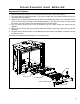
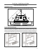
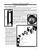

Flue Pipe Adaptor
Wall Framing
Wall Thimble
Fire Stop
Exhaust 4" Flex Pipe
Combusion Air 6 5/8" Flex Pipe
Wire Spacers
Horizontal Vent Termination
19
INSTALLATION INSTRUCTIONS:
1. Plan your installation and clearances to combustibles. Decide on a location for the unit that will meet
the clearances noted in the venting section, and any or all local code requirements.
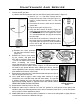
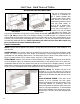
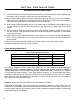
Wire
spacers
Figure 25: Wire Spacers.
2. Set the appliance in the desired location. Determine if any wall studs,
electrical wiring, or plumbing pipes are in the way of the venting system as
it passes through the exterior wall. The replace location should be adjusted
if obstructions are found in the wall.
3. Project a line from the center point of the ue outlet upward and outward to
the desired ue outlet location on the exterior wall. Using this center point,
Initial Installation
QUALIFIED INSTALLERS ONLY
Figure 26: Wire Spacer in Place.
scribe a 10” (25.4 cm) hole or square on the
wall. Cut the hole from the interior through
the exterior wall surfaces.
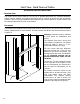
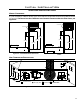
4. Frame the hole as shown in Figure 29.
5. Trim the wall thimble to match the wall
thickness as necessary. Install the wall
thimble and secure it to the inner wall
frame using four (4) 1½” wood screws. If
a wall is greater than 8” (203mm) in depth,
the clearance above the ex must be 4⅜”
(111mm)
Figure 27: Installation of Fireplace Horizontal Vent Kit.
6. Apply a bead of Mill-Pac Black
sealant to the new Ø4” (10 cm) by
5” (12.5 cm) provided ue collar
adaptor. Press the ue collar into
the ue outlet of the replace so
that the Mill-Pac seals the ue
collar to the ue outlet.
7. Stretch both the Ø4” (10 cm) ex
vent and the Ø6⅝” (16.25 cm) ex
intake liner to the length needed
to ensure the ex can be easily
connected to the vent terminal.
8. Slide the Ø6⅝” (16.25 cm) ex
intake liner over the ex vent.
Install four (4) wire spacers
around the ex pipe. Ensure the
wire spacers are positioned at
either end of the pipes, and at
each end of any elbows in the
liners (refer to Figure 25 and 26).