FOR INSTALLERS AND SERVICE TECHNICIANS ONLY GAS FIREPLACE SERVICE MANUAL Sherwood Industries Ltd. Duplication of this document is prohibited. All rights reserved.
This is a service guide designed by SHERWOOD INDUSTRIES LTD. We hope this manual will assist you to identify and correct operational concerns you might experience in all ENVIROGAS appliances. This service guide is designed for TRAINED SERVICE TECHNICIANS AND INSTALLERS. This guide is NOT to be used by the homeowner. If after reading this guide and following our recommendations and the problem still excists, please do-not hesitate to call our technical department. Technical Division SHERWOOD INDUSTRIES LTD.
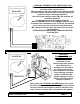
1(PILOT WILL NOT LIGHT NO SPARK A) IGNITION SYSTEM Make sure that wires are not broken, frayed and that all connections are tight at both the piezo ignitor and electrode. Replace with only manufactures parts Make sure that ceramic on the electrode is not broken. Carefully try to spin the porcelain. IF IT DOES, replace electrode. Make sure a 1/8” (3.175mm) gap is maintained between electrode and pilot hood. SEE PAGE 2 FIGURE 1. Replace electrode.
3.175mm Sherwood Industries Ltd.
B) PIEZO IGNITOR OK BUT PILOT WILL STILL NOT LIGHT Make sure all gas lines have been connected with no leaks. Correct if necessary, test for gas leaks in an approved manner. Make sure that the gas is “ON” (NG) Natural gas and (LP) Propane tanks are full. Correct if necessary. Make sure the appliance service valve is in the “ON” position. SEE PAGE 4 FIGURE 3. Turn service valve to the “ON” position. Test to make sure there is no air in the gas line. SEE PAGE 4 FIGURE 3.
EXPLODED VIEW S.I.T PILOT ASSEMBLY To remove pilot injector: Remove the two screws that hold the pilot assembly to the burner control assembly. Lift the assembly straight up being careful not to damage any components. Using a 10 mm wrench undo the securing nut on pilot tubing and pull tubing down to access injector. Being careful not to damage the ceramic spark electrode. Replace the injector and reinstall the pilot tubing, always to perform a gas leak test before lighting the pilot assembly.
3.5” wc BELOW 0 3.5” wc ABOVE 0 INLET GAS PRESSURE 7” wc (NG) NATURAL GAS NO PRESSURE 1.75” wc BELOW 0 1.75” wc ABOVE 0 OUTLET GAS PRESSURE 3.5 “ wc (NG) NATURAL GAS SUPPLY PRESSURES NATURAL GAS 50% TURN DOWN 33% TURN DOWN MAX SUPPLY PRESSURE MIN SUPPLY PRESSURE MAX SUPPLY PRESSURE MIN SUPPLY PRESSURE Sherwood Industries Ltd. 7” wc 5” wc 7” wc 4.5” wc ENVIRO PROPANE GAS 12” wc 11.5” wc 13” wc 10.
190 mv DC CHECKING THERMOPILE FOR PROPER VOLTAGE Place the leads of the multimeter on the TP/TH and TP terminals on the valve as shown. With the switch in the “ON” position, the readings should be approximately 190mV DC (this an average reading) or greater for proper Thermopile operation. The main burners may not come ON if the readings are less than 145mV DC. If a thermostat has been installed.
2) PILOT WILL NOT STAY LIT Use a manometer on the inlet side of the valve to measure gas pressure. Adjust inlet pressure or contact your gas supplier. Make sure the gas pressure is correct for type of fuel you are using. SEE PAGE 5 FIGURE 7. Thermocouple should be the same height as the pilot hood. Make sure pilot flame is engulfing the top 3/8” of the thermocouple. SEE PAGE 2 FIGURE 2. Adjust pilot as required. Check for clogged pilot injector. Make sure thermocouple connections on valve are tight.
S.I.T EUROSIT MODULATING 630 SERIES Sherwood Industries Ltd.
3) MAIN BURNERS WILL NOT LIGHT Make sure gas valve knob is in the “ON” position. SEE PAGE 8 FIGURE 6. Correct if necessary. Turn valve to the “ON” position. Make sure that the “ON-OFF THERMO” switch is in the “ON” position. Turn switch “ON”. Make sure that the thermostat is “NOT” in the lowest position. Turn thermostat “UP”. Replace damaged wires as necessary. Gently squeeze connectors with a pair of pliers and reinstall wires.
MAIN BURNERS WILL NOT LIGHT CON’T. Bypass spill switch with a jumper wire as shown. If the unit starts, replace the spill switch. DO NOT LEAVE BY PASSED IN. Check spill switch operation on B-vented models only SEE PAGE 10 FIGURE 9. Check the “ON-OFF” switch and thermostat for proper operation. Use a jumper wire. If the unit starts, replace switch if necessary. Make sure that the main burner orifices are not clogged or damaged. Remove the top tray. Remove orifice and clean. Replace if damaged.
4) MAIN BURNERS WILL NOT STAY LIT Adjust pilot if necessary. Make sure pilot flame engulfs the thermopile and does “NOT” have a yellow luminous flame. SEE PAGE 4 FIGURE 4. Check outlet gas pressure. Check for clogged pilot injector or blocked air inlet. Using a multimeter check thermopile. If not constant replace thermopile. Make sure millivolt readings from thermopile are constant. Make sure all wiring is not damaged or broken and all connections are tight. Correct if necessary. By pas spill switch.
Sherwood Industries Ltd.
SAMPLE DIRECT VENT CHIMNEY INSTALLATIONS ALL MODELS Sherwood Industries Ltd.
SAMPLE B-VENTED CHIMNEY INSTALLATIONS ALL MODELS INSERT MODELS MUST BE FULLY LINED AND SEALED Sherwood Industries Ltd.
5) SOOTING Make sure log placement is in the correct location. Correct to manufactures specifications. Correct if necessary. Outside air supply may be required on B-vented models. Make sure there is sufficient air supply. Check air shutter on the venturi tube for proper primary air adjustment. SEE PAGE 16. Increase primary air. Open air shutter. Make sure orifice matches that on the rating plate. Correct if necessary. Make sure outlet (manifold) pressure is correct.
IF THE AIR SHUTTER IS OPENED WIDER, THE FLAME COULD APPEAR ALMOST ALL BLUE WITH FLAME LIFTING BEING THE END RESULT IF OPENED TOO MUCH WITH THE AIR SHUTTER SET PROPERLY, THE FLAME WILL SIT ON THE BURNER PORT AND THE FLAME PATTERN WILL START AT THE BOTTOM WITH A BLUE FLAME THEN TURNING TO A WHITE ALMOST YELLOW FLAME WITH A SLIGHT ORANGE EDGE AS THE AIR SHUTTER IS CLOSED, THE FLAME COULD APPEAR TALLER WITH A VERY LAZY BLACK ORANGE TIPPED FLAME PRODUCING CARBON (SOOT) Sherwood Industries Ltd.
6) FLAME LIFTING A) B-VENTED MODELS Adjust air shutter, by closing shutter. DO NOT GO TOO FAR OR THE UNIT WILL SOOT. Check air shutter on the burner tube (venturi). Make sure there are no leaks in the venting system. Seal venting if necessary. Improper venting configuration. Correct if necessary. Make sure that manifold (outlet). Pressure is correct. Use a manometer to check gas pressure. SEE PAGE 5 FIGURE 7. Sherwood Industries Ltd.
B) DIRECT VENT MODELS Check air shutter on the burner tube (venturi). Adjust air shutter. Close until flame sits onto the burner ports. Seal exhaust tube with high temperature silicone. Also make sure that combustion air pipe is sealed. Make sure there are no leaks in the venting system. Make sure the unit is not recirculating flue products. Check flue for blockage or high wind situations. Make sure the gas pressure is correct for fuel being used.
7) BLOWER DIAGNOSIS ALL MODELS Check to make sure that the fan is plugged in. Make sure the fan control knob is in the “ON” position. Make sure the two wires are connected to the fan temperature sensor. Make sure that the two wires are connected to the blower. Make sure there are no broken, damaged or frayed wires. Make sure that the fan sensor is secure and that it is not damaged. If the blower does not work, replace the blower.
ORIFICE SIZING CHART DRILL# 70 69 68 1/32 67 66 65 64 63 62 61 60 59 58 57 56 3/64 55 54 53 1/16 52 51 50 49 48 5/64 47 46 45 44 43 42 3/32 41 40 39 38 37 36 7/64 35 34 SIZE .0280 .0292 .0310 .0313 .0320 .0330 .0350 .0360 .0370 .0380 .0390 .0400 .0410 .0420 .0430 .0465 .0469 .0520 .0550 .0595 .0625 .0635 .0670 .0700 .0730 .0760 .0781 .0785 .0810 .0820 .0860 .0890 .0935 .0938 .0960 .0980 .0995 .1015 .1040 .1065 .1094 .1100 .1110 SHERWOOD IDUSTRIES LTD. NATURAL GAS 3.5” 3.
STEP BY STEP SERVICE INSTRUCTIONS These appliances do require to be serviced. Our best recommendation is that the appliance be serviced (1) once a year, maybe just before the heating season starts. Annual service should and inspection should include: ⇒ ⇒ ⇒ ⇒ ⇒ ⇒ ⇒ ⇒ ⇒ ⇒ ⇒ ⇒ Open the two side panels or remove the face frame from the appliance. Vacuum all areas around the convection blower making sure there are no obstructions near the convection blower or in the impeller fan blades.
⇒ ⇒ ⇒ ⇒ Turn the switch to the “ON” position; check the millivolt readings at the thermopile make sure that the readings meet manufacters specifications. Turn the unit “OFF”. Install a manometer on the inlet side of the gas valve marked (E), re light the appliance make sure that the inlet pressure meets the manufactures specifications. Shut the unit “OFF” once again and do an outlet (manifold) pressure test.
10) GLOSSARY B-VENTED SYSTEM A venting system using only approved double wall pipe and approved B-vent components. This system also uses room air for proper venting action through the dilution air inlet mounted on the back of the unit. CONTINUITY TEST By using a multimeter set on OHMS, is determined if the circuit is complete, or continuous (no break in the circuit). DIRECT VENT SYSTEM A venting system sealed from the structure for both the exhaust gases and fresh air supply.