SHERWOOD INDUSTRIES IS AN ENVIRONMENTALLY RESPONSIBLE COMPANY. THIS MANUAL IS PRINTED ON RECYCLED PAPER. PLEASE KEEP THESE INSTRUCTIONS FOR FUTURE REFERENCE Sienna BY: SHERWOOD INDUSTRIES LTD OWNER’S MANUAL WHAT TO DO IF YOU SMELL GAS • Open windows/extinguish any open flame. • Do not try to light any appliance. • Do not touch any electrical switch or use any phone in your building. • Immediately call your gas supplier from a neighbour’s phone. Follow the gas supplier’s instructions.
Safety Precautions FOR SAFE INSTALLATION AND OPERATION OF YOUR “ENVIRO” HEATER, PLEASE CAREFULLY READ THE FOLLOWING INFORMATION: • All ENVIRO gas-fired appliances must be installed in accordance with their instructions. Carefully read all the instructions in this manual first. Consult the building authority having jurisdiction to determine the need for a permit prior to commencing the installation.
Table of Contents Safety Precautions.....................................................................................................2 Table of Contents......................................................................................................3 Codes And Approvals.................................................................................................4 Specifications............................................................................................................
Codes And Approvals DIRECT VENT: This type is identified by the suffix DV. This appliance draws all of its air for combustion from outside the dwelling, through a specially designed vent pipe system. This appliance has been tested and approved for installations from 0 feet to 4500 feet (1372 m) above sea level. BV: This Vented appliance draws all of its combustion air from the dwelling and must be vented using listed B or L vent. May also be vented through a conventional chimney using a chimney liner kit.
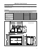
Specifications RATING LABEL LOCATION: The rating label is located under the control panel and is attached to a rectangular metal sheet that is chained to the fireplace. DIMENSIONS: Table 1: Sienna exterior dimensions. (Shaded dimensions shown in Figure 1 & 2.
Specifications 21" (533 mm) Sensor Flue 13 1/16" (333 mm) With Trim 46 1/8" (1171 mm) Without Trim 46" (1168 mm) 17 3/8" (441 mm) 1 3/8" (36 mm) With Trim 33 3/16" (343 mm) Without Trim 33" (338 mm) 30 1/2" (775 mm) 15 1/16" (383 mm) Figure 2: Sienna exterior dimensions; example 2.
Operating Instructions For Your Safety, Read Safety Precautions And Lighting Instructions Before Operating WARNING: IF YOU DO NOT FOLLOW THESE INSTRUCTIONS EXACTLY A FIRE OR EXPLOSION MAY RESULT, CAUSING PROPERTY DAMAGE, PERSONAL INJURY OF LOSS OF LIFE. PILOT LIGHTING INSTRUCTIONS: CAUTION: Hot while operating. Do not touch, severe burns may result. Keep children, clothing, furniture, gasoline or other flammable vapors away.
Operating Instructions For Your Safety, Read Safety Precautions And Lighting Instructions Before Operating BURNER LIGHTING: A) B) C) D) E) Make sure the pilot is lit. Turn gas control knob COUNTER CLOCKWISE to ON. Flip the burner switch to ON. Turn HI/LO knob to the desired flame height. Turn on all electrical power to the unit. NOTE: Check that all burner holes are lit. Figure 5. Control panel. TURN OFF UNIT: Flip switch to OFF to turn off burners only.
Maintenance And Service Warning: Failure to position the parts in accordance with this manual, or failure to use only parts specifically approved with this appliance, may result in property damage or personal injury. At least once a year, run through the following procedures to ensure the system is clean and working properly. Check the burner to see if all the ports are clear and clean. Check the pilot to make sure it is not blocked by anything.
Maintenance And Service TO BE INSTALLED BY A QUALIFIED SERVICE AGENCY ONLY FUEL CONVERSION: Warning: This conversion kit shall be installed by a qualified service agency in accordance with the manufacturer’s instructions and all applicable codes and requirements of the authority having jurisdiction. If the information in these instructions is not followed exactly, a fire, explosion or production of carbon monoxide may result causing property damage, personal injury or loss of life.
Initial Installation WARNING: Operation of this heater when not connected to a properly installed and maintained venting system can result in carbon monoxide (CO) poisoning and possible death. CLEARANCES TO COMBUSTIBLES: Maintain sufficient clearances for operation, service and maintenance. • A clearance of 25 1⁄2” (648 mm) minimum is required from the center of the unit to the sidewalls. • A 2” (51 mm) wide mantel can be mounted at a minimum height of 39” (991 mm) from the bottom of unit.
Initial Installation WARNING: Operation of this heater when not connected to a properly installed and maintained venting system can result in carbon monoxide (CO) poisoning and possible death. MINIMUM FIREPLACE SIZE: Table 2: Minimum dimensions of fireplace for Sienna to be installed into.
Initial Installation QUALIFIED INSTALLERS ONLY DIRECT VENT MODEL: WARNING: This appliance has been designed to draw room air for proper heat circulation from the sides of the unit. Blocking or modifying the louvers in any way can create hazardous situations. This model is vented with two (2) 3” aluminum or stainless steel flex vent leading into a co-linear to co-axial vent adaptor and using a vertical termination cap.
Initial Installation QUALIFIED INSTALLERS ONLY VENTING FIREPLACE INSERTS: The ENVIRO SIENNA may be installed and vented into any solid fuel fireplace that has been installed in accordance with the National, Provincial/State and local building codes and has been constructed of noncombustible materials. Before starting refer to PREPARING YOUR SIENNA FOR INSTALLATION and CONVERTING A DIRECT VENT FIREPLACE TO A B-VENT FIREPLACE. An approved chimney liner and rain cap must be used.
Initial Installation QUALIFIED INSTALLERS ONLY ELECTRICAL REQUIREMENTS: The fan is thermostatically controlled and it will not operate if the appliance is cold. A few minutes after the appliance is lit and the variable speed control is set at a desired setting, the fan will automatically turn on. The fan will automatically turn off after the appliance has cooled down.
Initial Installation QUALIFIED INSTALLERS ONLY GAS LINE CONNECTION: Warning: Only persons licensed to work with gas piping may make the necessary gas connections to this appliance. Gas Line Connection: •This fireplace is equipped with a certified flexible pipe located on the right side of the unit, terminating in a 3⁄8” male NPT fitting. Consult the local authorities for local codes or use the CAN/CGA B149 (1 or 2) installation code in Canada.
Initial Installation QUALIFIED INSTALLERS ONLY CONVERTING A DIRECT VENT FIREPLACE TO A B-VENT FIREPLACE: 1. Remove the Direct Vent chimney connector assembly by taking out the two (2) T-20 screws at the front of the unit. Push the assembly out from under the brackets at the back and remove (see Figure 16). 2. Remove the two (2) fresh air inlet covers from each side. Cover locations shown in Figure 16. 3.
Secondary Installation QUALIFIED INSTALLERS ONLY REPLACING THE BLOWER: 1. Turn the unit off and allow the unit to cool completely. 2. Remove the fascia or louvers, open the door (see “DOOR REMOVAL”), and remove the log set. 3. Remove the log support tray by lifting the back of the tray up and pull it out from under the lip. Take care to not knock the pilot and the side brick panels. 4. Remove the centre and top brick panels (see “REMOVING THE BRICK PANEL”). 5. Turn gas supply off and remove gas connection.
Secondary Installation DOOR REMOVAL: Open the door by removing the two (2) 5/16’’ bolts located at the top outside corners of the glass frame (see Figure 19). Lift the bottom of the door up and remove from unit (see Figure 20). CAUTION GLASS MAY SEPARATE FROM DOOR. Figure 19: Top bolts for glass door. Figure 20: Bottom hooks for glass door. INSTALLATION OF SURROUND PANEL: The Sienna must have one of the panels installed around the unit; the unit panel, the filler panel, or the filler panel with trim.
Secondary Installation LOG SET AND EMBER INSTALLATION: NOTE: The logs are fragile and should be handled gently. The placement of the logs is not arbitrary. If they are positioned incorrectly, the flames can be “pinched” and will not burn correctly. The burner, and a few of the logs come with locator pins, notches and ledges, which make alignment easier. Using the pictures provided, carefully set the logs in place (see Figures 24 through 29). Figure 24: The first log to be placed is the back log.
Secondary Installation Figure 27: The front end of the right/center log has a notch in it that is to rest around the right/center post of the grate. The back end of the log rests on the burner tray (see Figure 26). Ensure the log does not block any burn ports. Figure 27. Third Stage Log Set Installation. Figure 28: Once the logs are in position the provided rock wool can be placed irregularly in front of the burner.
Secondary Installation Figure 30. Sienna complete log set-up with embers burning. NOTE: While the glass is still removed, it is recommended that the gas line be purged by lighting the pilot. When lighting the fireplace for the first time since the log set and embers have been installed/replaced, watch for ignition at ALL the burner ports. If a long delay is noticed, turn the appliance off and wait for it to cool down.
Secondary Installation REMOVING THE BRICK PANEL: The brick panel set is fragile, handle with extreme care. The brick panel set comes pre-installed. The centre and top panel are the only panels that need to be removed if the complete gas and electrical tray assembly must be removed. The side panels may remain installed unless they are to be replaced. 2 1 1. Turn the unit off and allow the unit to cool completely. 2. Remove the fascia or louvers, open the door, and remove the log set.
Trouble Shooting Problem Possible Cause Solution Spark will not arc to the pilot after repeatedly pressing the spark ignitor Defective piezo ignitor • Check connections to ignitor. • If ignitor connections are good but no spark, replace ignitor. Broken spark electrode • Check for broken ceramic insulation, replace electrode if broken. Mis-aligned spark electrode • If spark is not arcing from electrode to pilot, loosen the screws on the pilot base, adjust and tighten.
Parts List- Unit Components Reference Number 1 2 3 3 4 4 4 4 4 5 6 7 8 9 10 11 12 13 14 15 16 17 18 19 20 21 22 23 24 Part Description 120°F Ceramic Fan Temperature Sensor 300°F (149°C) Manual Reset Spill Switch (Normally Closed) S.I.T. Nova Valve NG (50% turn down) S.I.T. Nova Valve LP (50% turn down) Thermocouple Spark Electrode with Ignitor Cable Thermopile Pilot Orifice NG Threaded Pilot Orifice LP Threaded Pilot Gasket S.I.T.
Parts Diagram - Components � �� October 2004 �� SIENNA - Components �� �� �� �� �� �� �� �� 26
Parts Diagram - Burner �� �� �� � � �� � �� � � � � SIENNA - Burner October 2004 � 27
Parts List - Options Reference Number 1A 1A 1A 1A 2A 3A 4A 5A 6A 7A 28 Option Description The Cottage Trim Kit - Gold The Cottage Trim Kit - Pewter The Cottage Trim Kit - Antique Copper The Cottage Trim Kit - Painted Charcoal Cape Cod Doors Unit Panel & Keystone Cottage Filler Panel Louvers (set of 2) Panel Trim Set 46” x 30” (117cm x 76cm) - Black Part Number 50-548 50-549 50-550 50-694 50-1097 50-1108 50-1109 50-1110 50-1111 50-1113
Parts Diagram - Options �� �� �� �� �� �� �� SIENNA - Options October 2004 29
Warranty Sherwood Industries Ltd. offers a Limited Lifetime Warranty on this gas product. This Limited Lifetime Warranty covers the appliance for a period of seven years from the date of installation. This warranty applies only to the original owner in the original location. Covered under the lifetime warranty are: the surround, the chassis and the heat exchanger. These steel components are covered against manufacturer’s defects for seven (7) years and the labour for the first year.
Installation Data Sheet The following information must be recorded by the installer for warranty purposes and future reference.