Electronic Multi-Zone Environmental Alarm System Installation/Owner’s Manual D-011-0152
Limitations of the Alarm System or Device While your alarm system or device is reliable and sophisticated, it does not offer guaranteed protection against burglary, fire or other emergency. Any security product, whether commercial or residential, is subject to compromise or failure-to-warn for a variety of reasons. These include: • Individuals may gain access through unprotected openings or have the technical sophistication to bypass an alarm sensor or disconnect an alarm warning device.
Table of Contents General Information............................................................................................................................... 1 Overview ............................................................................................................................................ 1 How to Use This Manual.................................................................................................................... 2 Block Diagrams......................................
Operation .............................................................................................................................................. Monitoring Environmental Conditions .............................................................................................. Viewing Sensor Settings .................................................................................................................. Viewing Active Alarms ...................................................................
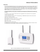
General Information Overview The EnviroAlert® EA800 Multi-Zone Environmental Alarm System monitors the environmental conditions detected by the sensors connected to the base unit, and provides alarm signals when monitored conditions at any of the sensors exceed the user-programmable HIGH LIMIT or LOW LIMIT set points. The alarm signals are provided via relay outputs that can operate with process controls, security systems, or other similar automated equipment.
How to Use This Manual How to Use This Manual This manual is organized into sections that guide you through the installation process, then describe how to use the EA800 and change its programmed settings if necessary. Some troubleshooting guidelines are provided, and the appendices contain forms for you to photocopy and use to record the programmed settings of the EA800 and the monitoring system setup.
General Information Block Diagrams Figure 2 shows a block diagram of the base unit interfaces and functions. The EA800 provides eight relays for indicating when a programmed alarm limit has been exceeded or a warning condition exists. An additional AUX (Auxiliary) Output relay provides an output signal to an optional audible alarm or strobe that is activated whenever an alarm condition exists.
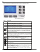
Symbols on the Product or Manual Labeling Symbols on the Product or Manual Labeling Symbols appearing on the product labeling, packaging, and/or in this manual are shown and described in Table 1. Table 1 Symbols on Product or Manual Symbol Definition Attention, consult accompanying documents or statements. For product disposal, ensure the following: • Do not dispose of this product as unsorted municipal waste. • Collect this product separately. • Use collection and return systems available to you.
General Information Monitoring Screens The EA800 user interface is menu-based. During normal system monitoring, one of the following three screens is displayed depending on the current state of the programmed sensors: The MONITORING (home) screen is displayed when there are no active alarms. The screen lists all programmed sensors connected to the base unit and their current reading or state.
Keys Keys Figure 4 shows the base unit display and entry keys. The keys are described in Table 2. Figure 4 EA800 Base Unit Keys Table 2 Key Key Functions Function F1 This key's function changes as determined by the software. Its current function is displayed immediately above the key on the display. F2 This key's function changes as determined by the software. Its current function is displayed immediately above the key on the display. F3 This key's function changes as determined by the software.
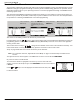
General Information Base Unit Connections Figure 5 shows the EA800 base unit's connections and Table 3 describes the functions of each connection. Note: The base unit has four wired sensor inputs and four wireless RF sensor inputs.
Access Control and Passwords Table 3 EA800 Base Unit Connector Functions — continued Connector J6 Designation Function INPUT 1 Wired input for Relay 1 external temperature, water, 4-20mA, contact closure, or humidity sensor. INPUT 2 Wired input for Relay 2 external temperature, water, 4-20mA, contact closure, or humidity sensor. INPUT 3 Wired input for Relay 3 external temperature, water, 4-20mA, contact closure, or humidity sensor.
General Information System Configuration Parameters The EA800 base unit requires certain system level information as outlined in Table 4. Table 4 System Configuration Parameters Parameter Date Format Selections • MM/DD/YYYY • DD/MM/YYYY Factory Default Description MM/DD/YYYY Sets the desired date format for all event time stamps. Time Format • 12-hour • 24-hour 24-hour Sets the desired time format for all event time stamps.
Sensors Sensors A variety of sensors may be used with the EA800 base unit to provide environmental status and information. These include the following: ■ Wired Sensors: Relays 1 through 4 are for use with sensors wired to the base unit.
General Information Humidity Sensors Table 6 lists the humidity sensors available for use with the EA800 Alarm System. Table 6 EA800 Compatible Humidity Sensors Sensor Part Number Description Operating Range/Parameters HA-III+ PN M-001-0091 Humidity monitoring module 5% to 95% rh (non-condensing) Wireless Humidity PN M-001-0126 Wireless humidity monitoring module 5% to 95% rh (non-condensing) 4-20mA Sensors Theory of Operation Industry standard 4-20mA sensors can be used with the EA800.
Sensors Power Supply / Sensor Voltage Selection In order to determine the power supply voltage necessary to ensure correct full-scale operation, it is necessary to identify all voltage drops within the current loop. Figures 6 and 7 show an EA800 drop of 4.0 VDC. This value accounts for the voltage drop generated by connecting the 4-20mA sensor to the EA800 using 1000 feet of 22 AWG wire.
General Information Water Sensors Table 8 lists the water sensors available for use with the EA800 Alarm System. Use of water sensors requires that at least one supervised water sensor be used. Up to five additional unsupervised water sensors may be added in parallel on the same input where the supervised water sensor is configured.
Sensors Sensor Parameter Descriptions This section provides a description of each sensor parameter. Table 11 Sensor Parameter Descriptions Parameter Applicable to Sensors Sensor Name All Description A name used to identify the sensor in the alarm system. Select a name readily identified by the viewer. The sensor name is displayed on the Main screen during a no-alarm condition and on the Alarm screen during an alarm condition.
General Information Table 11 Sensor Parameter Descriptions — continued Parameter Applicable to Sensors Description High Alarm Limit • Blue, Red and White The High Alarm Limit sets the value that trips the high alarm when temperature sensors exceeded. • HA-III+ • 4-20mA sensor • Wireless humidity sensor • Wireless temperature sensor Alarm Delay Time All This sets the time period that an alarm condition can exist before the alarm is triggered.
Relay Operation 16 D-011-0152
Preparation Before you begin installation, ensure that you properly plan the alarm system. During the planning phase you will generate all the documentation you need to successfully install the EA800 base unit and sensors in the alarm system. This is important because complete and accurate installation documentation aids in system maintenance later.
5. Complete the copy of Appendix B: Planning Worksheet for the facility in which the EA800 system is to be installed. This must include all monitored areas for the total security system so that you know how many EA800 base units are needed. 6. Determine the sensors required from the Planning Worksheet you completed and the information provided for each sensor type in “System Configuration”. Enter these in the copy of the System Configuration Record you made.
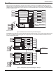
Preparation From 11-26 VDC power supply Power In Aux Power Out J6 J5 Input 1 Input 2 Input 3 Input 4 J13 J14 J2 J8 Output 1 NO COM NC Output 2 Output 3 Output 4 Output 5 Output 6 Output 7 Output 8 NO COM NC NO COM NC NO COM NC NO COM NC NO COM NC NO COM NC NO COM NC Aux NO COM NC To "alarm-on-closed" loop circuit (power supplied via loop) Figure 9 Typical Alarm Loop Wiring Configuration (External Power) From 11-26VDC power supply Power In Aux Power Out J6 J5 Input 1 Input 2
12. Create an interconnect wiring diagram for the system. Identify the location of each sensor An example of a system map is shown in Figure 11. This example illustrates a system that includes multiple EA800 Multi-Zone Environmental Alarm systems, a Winland EA400 Multi-Zone Environmental Alarm system, and a Winland EA200 Multi-Zone Environmental Alarm system.
Installation Tools and Supplies Required Ensure that you have the following prior to starting the installation: ■ Phillips Screwdriver ■ Mounting hardware for the EA800 base unit and any optional sensor units ■ If required, a drill and the appropriate drill bits ■ Wire stripper ■ Sensors (not supplied; see “Accessories” on page 54) ■ Sensor Wiring (typically 18-22 AWG twisted-pair; not supplied) ■ Alarm Wiring (typically 18-22 AWG; see EA800 Output (Alarm) Connections) ■ Power sources Power Requirements Al
Install the Wired Sensors 2. Mount the mounting plate as follows: ■ Mounting to 3-gang enclosure: Use four (4) machine screws to secure the mounting plate to the mating holes in the 3-gang enclosure. ■ Mounting to drywall surface: Place the mounting plate in mounting position. Mark the four mounting hole locations. Install drywall anchors and secure the mounting plate to the anchors. Note: If wall-mounted, prepare a wiring access hole at this time.
Installation Note: Verify that the wireless sensors can communicate with the base unit as outlined in the following procedure before permanently mounting them. 1. Remove the cover from the wireless sensors and record the MAC addresses (see Figure 12) of each wireless sensor on the Configuration Worksheet you completed during the preparation phase. The MAC address is printed on a label affixed to each wireless sensor’s printed circuit board (PCB) and is used to identify each sensor during programming.
Connecting Wired Temperature, Contact Closure, and Water Bug Sensors Note: It may take a few minutes for the base unit to detect the wireless sensors. At this point the NEW WIRELESS SENSOR screen is displayed and an arrow moves from left to right indicating that the EA800 is waiting to receive sensor ID data. When the EA800 has communicated with the reachable sensors the SELECT SENSOR screen displays a list of wireless sensors detected.
Installation Connecting Wired HA-III+ Humidity Sensors 1. Make certain the sensor's wiring is passed through the opening in the mounting plate. 2. Remove the adapter from the correct input connector headers by pulling the adapter up and off of the circuit board header connectors. 3. Strip the ends of each of the sensor's wires as indicated by the gauge on adapter you just removed. 4.
Connecting Wired 4-20mA Sensors Connecting Wired 4-20mA Sensors 1. Make certain the sensor's wiring is passed through the opening in the mounting plate. 2. Remove the adapter from the correct input connector headers by pulling the adapter up and off of the circuit board header connectors. 3. Strip the ends of each of the sensor's wires as indicated by the gauge on adapter you just removed. 4.
Installation Connecting the EA800 Alarm Outputs ! CAUTION If the EA800 base unit will be connected to a remote alarm panel, do not connect the base unit to the alarm panel until after sensor connection and configuration is complete. Connecting the remote alarm panel before configuring the EA800 sensors will result in false alarms at the remote panel. 1. If alarm loops will be controlled by the EA800, install all required wiring from alarm loops to the EA800 mounting location. 2.
Programming Accessing the MAIN MENU for Programming 1. If not already powered up, apply power to the EA800 base unit. During the boot process: ■ The Winland Electronics splash screen is displayed. ■ The system verifies flash memory, as indicated by FLASH BOOT at the bottom of the screen. ■ The About screen is displayed. ■ The MONITORING screen is displayed. UNLOCK appears above the F1 soft key. 2. Follow the steps below to unlock the keypad and access the MAIN MENU screen.
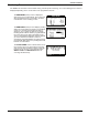
Installation 3. Enter the SYSTEM menu and then select the CONFIGURATION menu as shown below. : 4. The default date format is MM/DD/YYYY. If you prefer DD/MM/YYYY format, from the CONFIGURATION menu, set the DATE FORMAT as appropriate for your region. Choose setting for your region. 5. F3 Press F3 to confirm your selection. When the CONFIGURATION menu is displayed, skip TIME FORMAT if you want to use the default time format of 24-hour clock.
Programming Choose appropriate setting. 7. Press F3 to confirm your selection. When the CONFIGURATION menu is displayed, select and set BUZZER as shown below. The BUZZER setting enables/disables the audible alarm buzzer. ! Selecting DISABLED for this parameter turns the audible alarm buzzer off completely. No audible alarm tone will sound when an alarm occurs if DISABLED is selected. WARNING Choose appropriate setting. 8. F3 F3 Press F3 to confirm your selection.
Installation Setting the Current Date Unlock the EA800 to continue programming if necessary. See “Accessing the MAIN MENU for Programming” on page 28. From the MAIN MENU, use the arrow keys to select SYSTEM, then select Set Date and set the current date as shown below. Note: To go back or to skip a step, press the PREV (F2) or NEXT (F3) keys. To cancel, press F1. Example shown, set values as appropriate for your system.
Programming Setting the Time Unlock the EA800 to continue programming if necessary. See “Accessing the MAIN MENU for Programming” on page 28. From the MAIN MENU, use the arrow keys to select SYSTEM, then select Set Time and set the current time as shown below. If your region uses Daylight Savings Time and you want the EA800 to display the correct time, you must change the time setting manually when Daylight Savings Time starts and ends.
Installation Adding Wireless Sensors Go to the appropriate section for the wireless sensor to be added: ■ Wireless Temperature Sensor: See “Adding a Wireless Temperature Sensor” on page 33 ■ Wireless Humidity Sensor: See “Adding a Wireless Humidity Sensor” on page 37 ■ Wireless Multi-Function Sensor: See “Adding a Wireless Multi-Function Sensor Using a Wired Temperature Sensor” on page 35.
Adding Wireless Sensors Note: To enter numeric values, use the arrow keys. To advance the cursor to the next digit when entering numeric values, press the NEXT soft key (F3). To return to a previous digit, press the PREV soft key (F2). The Hysteresis setting helps prevent alarms from being set and reset continually if the environment is at or near the alarm set point by providing an acceptable variance.
Installation Adding a Wireless Multi-Function Sensor Using a Wired Temperature Sensor Wireless multi-function sensors are physically connected to wired sensors located elsewhere and provide a transmitter to send the signals monitored by the wired sensor to the base unit. To add a wireless multi-function sensor, do the following: 1. Unlock the base unit if necessary to continue programming. See “Accessing the MAIN MENU for Programming” on page 28. 2.
Adding Wireless Sensors When setting numeric values, use the arrow keys to change the value. Use the PREV and NEXT soft keys to move the cursor to the next or previous digit. Press the ENTER key to enter the value. Example shown, set values as appropriate for your system. F3 36 This is the start screen for the next sensor to be added, if any.
Installation Adding a Wireless Humidity Sensor The Hysteresis setting helps prevent alarms from being set and reset continually if the environment is at or near the alarm set point by providing an acceptable variance. For example, if HYSTERESIS is set at 1 and the sensor High Alarm Limit is set at +95, the sensor reading must decrease to +94 (+95 minus 1) in order for the humidity alarm condition to reset to a no-alarm condition.
Adding Wireless Sensors Adding a Wireless Multi-Function Sensor Using a Wired WaterBug Sensor Wireless multi-function sensors are physically connected to wired sensors located elsewhere and provide a transmitter to send the signals monitored by the wired sensor to the base unit. To add a wireless multi-function sensor, do the following: 1. Unlock the base unit if necessary to continue programming. See “Accessing the MAIN MENU for Programming” on page 28. 2.
Installation Example shown, set values as appropriate for your system. F3 D-011-0152 This is the start screen for the next sensor to be added, if any.
Adding Wireless Sensors Adding a Wireless Multi-Function Sensor Using a Wired Contact Closure Sensor Wireless multi-function sensors are physically connected to wired sensors located elsewhere and provide a transmitter to send the signals monitored by the wired sensor to the base unit. To add a wireless multi-function sensor, do the following: 1. Unlock the base unit if necessary to continue programming. See “Accessing the MAIN MENU for Programming” on page 28. 2.
Installation Example shown, set values as appropriate for your system. Select N.O. Contact or as appropriate. N.C. Contact F3 D-011-0152 This is the start screen for the next sensor to be added, if any.
Adding Wireless Sensors Verify Wireless Signal Strength After temporarily mounting the wireless sensors in the desired location, verify the signal strength at the base unit by performing the following procedure to verify the signal strength of each programmed wireless sensor. It may take as long as 30 seconds to acquire the current signal strength. Perform the following procedure to verify the signal strength of each programmed wireless sensor.
Installation Adding Wired Sensors ■ Low temperature sensors - Blue Thermistor Probes: See “Adding a Wired Temperature Sensor” on page 43. ■ High temperature sensors - Red Thermistor Probes: See “Adding a Wired Temperature Sensor” on page 43. ■ Ultra Low temperature sensors - White Thermistor Probes: See “Adding a Wired Temperature Sensor” on page 43. ■ HA-III+ humidity sensor: See “Adding a Wired HA-III+ Humidity Sensor” on page 44. ■ WaterBug sensor: See “Adding a Wired WaterBug Sensor” on page 45. ■ N.
Adding Wired Sensors Adding a Wired HA-III+ Humidity Sensor To add an HA-III+ humidity sensor perform the following procedure. Example shown, set values as appropriate for your system. NOTE: The sensor number must match the input number (J6 ) used by the sensor or an alarm may result. F3 This is the start screen for the next sensor to be added, if any.
Installation Adding a Wired WaterBug Sensor To add a WaterBug sensor perform the following procedure: Note: A supervised WaterBug sensor must be used. Example shown, set values as appropriate for your system. NOTE: The sensor number must match the input number (J6 ) used by the sensor or an alarm may result. F3 This is the start screen for the next sensor to be added, if any.
Adding Wired Sensors Adding a Wired Contact Closure Sensor The following procedure shown adds a N.O. contact closure sensor but is the same for N.C. contact closure sensor. Example shown, set values as appropriate for your system. NOTE: The sensor number must match the input number (J6 ) used by the sensor or an alarm may result. Select N.O. Contact or as appropriate. N.C. Contact F3 This is the start screen for the next sensor to be added, if any.
Installation Adding a 4-20mA Sensor To add a 4-20mA sensor, perform the following procedure. There are some additional parameters to configure with this type of sensor, including Unit of Measure and Resolution. 4-20mA sensors can be used for monitoring a variety of conditions because the measured value corresponds to a current level, which is configured to represent the conditions being monitored. Follow the steps outlined below to program a 4-20mA sensor.
Configuring the Relays Configuring the Relays When all sensors have been added, you must configure the relays so that the outputs indicate the monitored conditions correctly. Perform the following procedure to configure all relays used: Note: The default relay settings are: • Relays 1-8 (Active Condition = Alarm Only); • Aux Relay (Active Condition = Alarm or Warning); • All Relays (No Alarm - Relay State = De-Energized) If these defaults are acceptable, it is not necessary to configure the relays.
Operation This chapter provides instructions for doing the following: ■ “Monitoring Environmental Conditions” on page 49 ■ “Viewing Sensor Settings” on page 50 ■ “Viewing Active Alarms” on page 50 ■ “Viewing the Alarm Log” on page 51 ■ “Viewing Pending Alarm Information” on page 51 ■ “Viewing Limit Settings” on page 52 ■ “Viewing the Event Log” on page 52 ■ “Viewing the Sensor Log” on page 53 ■ “Viewing Firmware Information” on page 53 ■ “Viewing RF Information” on page 54 Monitoring Environmental Conditio
Viewing Sensor Settings Viewing Sensor Settings You can view the readings of each installed sensor on the MONITORING screen. To view details of a sensor’s programmed settings and current readings on one screen perform the procedure shown below. Note: The MAIN MENU screen shown in the example procedure is displayed when the system is locked. Sensor settings may also be viewed when the system is unlocked. Use the arrow keys to highlight the desired menu item.
Operation Viewing the Alarm Log This alarm log is a quick view of the 20 most recent alarms. Up to 100 alarms can be reviewed by selecting Data Log from the MAIN MENU, then selecting View Alarm Log. To review the alarm history and review a specific alarm stored in the log, perform the following procedure. Note: The MAIN MENU screen shown in the example procedure is displayed when the system is locked. This alarm log may also be viewed when the system is unlocked.
Viewing Limit Settings Viewing Limit Settings To view the current readings and the limits of a sensor that is not in an alarm state perform the following procedure: To return to Active Alarm or Monitoring screen. Viewing the Event Log The EA800 Alarm System logs up to 100 events in its Event Log. At the minimum, the following events are logged: ■ System power on: the date and time when the EA800 was powered on. ■ Sensor added: indicates that a sensor was added.
Operation Viewing the Sensor Log The sensor log provides a history of the environmental conditions for all installed sensors at a glance. Up to 100 data sets are stored in the sensor log. To view the sensor log, perform the following procedure: Press arrow keys to scroll up or down through the logged data. OR To return to Active Alarm or Monitoring screen. Viewing Firmware Information The About EA800 menu item displays the currently running firmware version.
Viewing RF Information Viewing RF Information The ABOUT RF screen displays the EA800 base unit’s MAC address, the RF channel currently in use, the RF communications protocol version, and the RF subsystem’s firmware version. To view the RF settings, perform the following procedure: Note: The firmware revision number shown indicates the firmware version currently installed. F1 54 Displays the Active Alarm or Monitoring screen.
Maintenance This chapter contains instructions on performing the following maintenance tasks: ■ Lock/unlock the base unit: See “Locking and Unlocking the EA800” on page 55 ■ Pausing/resuming sensor monitoring: See “Pausing Monitoring and Cancelling Pause” on page 56 ■ Adding sensors: See “Adding a Sensor” on page 57 ■ Replacing a sensor. See “Replacing a Sensor” on page 57 ■ Deleting a sensor. See “Deleting a Sensor” on page 59 ■ Reprogramming a Relay.
Pausing Monitoring and Cancelling Pause Pausing Monitoring and Cancelling Pause To prevent false alarms when performing maintenance, pause sensor monitoring. Pausing stops monitoring and ignores active alarms for a 30-minute period. When the pause function times out, monitoring automatically starts.
Maintenance Adding a Sensor The procedure for adding a sensor to an existing system is the same as for a new system. See “Install the Wired Sensors” on page 22 or “Install the Wireless Sensors” on page 22 for instructions on physically installing the sensor and then programming the sensor in the EA800 base unit. Note: See “Pausing Monitoring and Cancelling Pause” on page 56 and pause the base unit before you begin so you can set up the sensor without tripping the alarm.
Editing Sensor Parameters 5. If the detected new sensor is not the same type as the replaced sensor, the INVALID SENSOR TYPE screen is displayed. Press OK (F3) to return to the SENSORS screen: 6. Do one of the following: • Replace the physical sensor with one that matches the type of the replaced sensor and repeat this procedure. • Delete the sensor from the base unit and replace with the new sensor (of a different type). See “Deleting a Sensor” on page 59 and “Adding a Sensor” on page 57. 7.
Maintenance Reprogramming a Relay Note: Ensure that the system’s Configuration Worksheets are updated to document any changes. A Relay can be reprogrammed as desired at any time. Perform the procedure outlined in “Configuring the Relays” on page 48 to reprogram any relay in the system. Deleting a Sensor Note: Update the system’s Configuration Worksheets to document any changes.
Changing the Date Format Changing the Date Format Note: Update the system’s Configuration Worksheets to document any changes. Note: The default date format is MM/DD/YYYY. To change the date format perform the following procedure: Unlock the EA800 as shown in “Locking and Unlocking the EA800” on page 55 F3 Changing the Time Format Note: Update the system’s Configuration Worksheets to document any changes. Note: The default time format is 24 HR.
Maintenance Changing the Date or Time Setting To change the date see “Setting the Current Date” on page 31. If your region uses Daylight Savings Time and you want the EA800 to display the correct time, you must change the time setting manually when Daylight Savings Time starts and ends. See “Setting the Time” on page 32. Changing Sensor Data Collection Frequency Note: Update the system’s Configuration Worksheets to document any changes. Note: The default collection frequency is 5 Minutes.
Changing the Buzzer Setting Changing the Buzzer Setting ! WARNING Changing the buzzer setting to DISABLED turns off the audible alarm tone from the base unit. Do not disable the buzzer unless you are sure you do not want the base unit to emit an audible tone when an alarm occurs. The active condition of the buzzer mirrors what is assigned to the auxiliary relay. Note: Update the system’s Configuration Worksheets to document any changes.
Maintenance Changing the Password Note: Update the system’s Configuration Worksheets to document any changes. Note: If you do not enter a valid password you will not be allowed to change the selected password. The default password (0800) cannot be changed or deleted. One user-configurable password may be set in addition to the default 0800 password.
Clearing the Alarm Log Clearing the Alarm Log To clear all stored alarm records perform the following procedure: Note: You cannot clear the Event Log. Unlock the EA800 as shown in “Locking and Unlocking the EA800” on page 55 F3 F3 Clearing the Sensor Log To clear all stored sensor records perform the following procedure: Note: You cannot clear the Event Log.
Maintenance Updating the Firmware Download the latest firmware from www.winland.com to your computer, then save it to a USB jump drive before performing the procedure for updating the firmware as shown below. Unlock as shown in “Locking and Unlocking the EA800” on page 55 If this message appears, insert the USB drive with new firmware into the USB port. During the process, the UPDATING FLASH screen is displayed.
Saving Configuration Settings Saving Configuration Settings You can export the configuration settings from the EA800 to serve as an archive for the system or as a template for quickly programming other systems. The configuration data is stored in a machine-readable format. To export configuration to a USB drive perform the following procedure: Unlock as shown in “Locking and Unlocking the EA800” on page 55 If this message appears, insert the USB drive with the configuration into the USB port.
Maintenance Loading Configuration Settings You can load configuration settings from a previously installed EA800 to serve as the template for the system being installed or updated. To load a configuration from a USB drive, insert the USB drive into the USB port and perform the following procedure: Unlock the EA800 as shown in “Locking and Unlocking the EA800” on page 55. This message appears only if no USB drive is present. Select the configuration file to download.
Exporting the Stored Logs Exporting the Stored Logs You can export the logs stored in the EA800 for archiving or later review. The export procedure exports the alarm log, data log, and event log files. To export the logfiles perform the following procedure: Unlock as shown in “Locking and Unlocking the EA800” on page 55 Appears only if a USB drive is not installed The screen displays the progress of the data export. Remove USB drive when export is complete.
Maintenance Exported Event Data The following is an example of exported event data: 12/24/2007 12/24/2007 12/25/2007 12/25/2007 12/25/2007 12/25/2007 12/25/2007 07:06:03 07:10:50 02:27:14 02:27:50 02:36:02 03:08:55 03:11:19 PM,Sensor PM,Sensor PM,System PM,Sensor PM,Sensor PM,Sensor PM,Sensor deleted,1 added,1 power on,1 deleted,1 added,1 deleted,1 added,1 The data presented provides the following event information: Date and time of event Event description Code (For Factory Use) 12/24/2007 07:06:03
Exporting the Stored Logs 70 D-011-0152
Troubleshooting Operating or setup errors are indicated by flashing data on the display. Often, a programming error also results in an alarm for the misprogrammed relay. The table below shows and describes common error displays, along with corrective action. For updated information, go to the EA800 page at www.winland.com and look for the troubleshooting section. Table 13 Troubleshooting Symptom Temperature reading indicates maximum when temperature is actually less.
Verifying RF Signal Strength Verifying RF Signal Strength Viewing Signal Strength for a Wireless Sensor To verify the RF signal strength received by the EA800 perform the following procedure: Unlock the EA800 as shown in “Locking and Unlocking the EA800” on page 55 F3 To return to SELECT SENSOR screen To return to home screen. If the remote sensor transmitter you are verifying is battery powered, it may take up to 30 seconds for the base unit to receive a transmission from the remote sensor.
Specifications Base Unit and Sensor Specifications The following table lists the specifications for the EA800 base unit, sensors, and accessories. Table 14 Specifications Item Specification Dimensions Approximately 230 mm x 199 mm x 55 mm(“9.375 H x 8.125" W x 2.25" D) Weight Base Unit: 0.27 kg (0.6 lb.) Wireless Sensors: 0.11 kg (0.26 lb.) with batteries Mounting The EA800 base unit is mountable directly to 3-gang standard electrical enclosure using pre-drilled holes on the EA800 rear case.
Accessories Table 14 Specifications — continued Item Specification Wired Water Presence Sensor: 2-wire; maximum 304 m (1000 ft.) cabling length Wired 4-20mA Sensor EA800 load (160 Ohms maximum) (9) Form C with 3-terminal NC/COM/NO connections. Relay Outputs Note: There are 8 primary relays (1 dedicated for each sensor) and 1 auxiliary relay. Relay Contact Ratings Max 30VDC @ 1 amp resistive. Not for use with AC power. Relay Logic Each relay is user configurable.
Appendix A: Screen Maps Appendix A: Screen Maps The figures in this Appendix illustrate the flow of all EA800 screens. The displayed screen is dependent on whether an alarm is active or not. Figure 17.
The displayed screen is dependent on whether an alarm is active or not. See Figure 19 See Figure 22 See Figure 24 See Figure 23 Figure 18.
Appendix A: Screen Maps See Figure 20 See Figure 21 Figure 19.
Common Name screen is dependent on the sensor being added. If multi-function only Parameter screens depend on the sensor being installed. Figure 20.
Appendix A: Screen Maps Screen displayed is dependent on the sensor type. Figure 21. Edit Sensor Screen Map Figure 22.
Figure 23.
Appendix A: Screen Maps Dependent on format See Figure 25 Figure 24.
Figure 25.
Appendix B: Planning Worksheet Appendix B: Planning Worksheet Note: Photocopy and complete a copy of this worksheet for each system.
84 D-011-0152
Sensor Connection Wire Color/ Designation D-011-0152 Input 1 Input 2 Input 3 Input 4 (-) + (-) + J5 Power In Aux Power Out EA800 ___ (-) + (-) + (-) + (-) + J6 Output 1 Output 2 Output 3 Output 4 Output 5 Output 6 Output 7 Output 8 Aux NO NC COM NO NC COM NO NC COM NO NC COM NO NC COM NO NC COM NO NC COM NO NC COM NO NC COM Wire Color/ Designation Alarm Panel Connection Appendix C: Wiring Diagram Appendix C: Wiring Diagram Note: Photocopy and complete copy of this diagram for eac
86 D-011-0152
Appendix D: System Configuration Record Appendix D: System Configuration Record Note: Photocopy this appendix and complete a copy for each EA800 base unit in the system.
EA800 Environmental Alarm System Configuration Form Sensor 2 Settings Sensor Model Sensor Name Physical Location Parameter Settings Unit of Measure: Resolution: Operational Parameters: Low Scaled Value: High Scaled Value: Hysteresis: Low Alarm Limit High Alarm Limit: Alarm Delay Time: No Alarm - Relay State: Notes: Active Condition: Sensor 3 Settings Sensor Model Sensor Name Physical Location Parameter Setting Unit of Measure: Operational Parameters: Resolution: Low Scaled Value: High Scaled Va
Appendix D: System Configuration Record EA800 Environmental Alarm System Configuration Form Sensor 4 Settings Sensor Model Sensor Name Physical Location Parameter Settings Unit of Measure: Resolution: Operational Parameters: Low Scaled Value: High Scaled Value: Hysteresis: Low Alarm Limit High Alarm Limit: Alarm Delay Time: No Alarm - Relay State: Notes: Active Condition: Sensor 5 Settings (wireless) Sensor Model Sensor Name Physical Location Parameter Settings Unit of Measure: Resolution: Opera
EA800 Environmental Alarm System Configuration Form Sensor 6 Settings (wireless) Sensor Model Sensor Name Physical Location Parameter Settings Unit of Measure: Resolution: Operational Parameters: Low Scaled Value: High Scaled Value: Hysteresis: Low Alarm Limit Installed LQI (in bars): High Alarm Limit: MAC Address: Alarm Delay Time: Notes: No Alarm - Relay State: Active Condition: Sensor 7 Settings (wireless) Sensor Model Sensor Name Physical Location Parameter Settings Unit of Measure: Reso
Appendix D: System Configuration Record EA800 Environmental Alarm System Configuration Form Sensor Model Sensor Name Physical Location Parameter Settings Unit of Measure: Resolution: Operational Parameters: Low Scaled Value: High Scaled Value: Hysteresis: Low Alarm Limit Installed LQI (in bars): High Alarm Limit: MAC Address: Alarm Delay Time: Notes: No Alarm - Relay State: Active Condition: D-011-0152 91
92 D-011-0152
Warranty and Service Information Winland Electronics, Inc. ("Winland") warrants to the end user/purchaser that each product of its manufacture shall be free from defects in material and factory workmanship for a period of two (2) years from the date of purchase, when properly installed and operated under normal conditions according to Winland's instruction.
Manufactured in the U.S.A by Winland Electronics 1950 Excel Drive, Mankato, MN, 56001 Outside MN Phone: 1-800-635-4269 Phone: 507-625-7231 Fax: 507-387-2488 ©Winland Electronics, Inc. 2008 www.winland.com D-011-0152 Rev.