
Home Security System User Manual
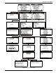

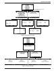

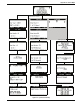
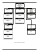


Appendix C: Wiring Diagram
D
-
011
-
0152
85
Appendix C: Wiring Diagram
Note: Photocopy and complete copy of this diagram for each EA800 to be installed in the system.
Power
In
Aux
Power
Out
J6
J5
Input 1
Input 2
Input 3
Input 4
(-)
+
(-)
+
(-)
+
(-)
+
(-)
+
(-)
+
Output 1
Output 2
Output 3
Output 4
Output 5
Output 6
Output 7
Output 8
Aux
NC
COM
NO
NC
COM
NO
NC
COM
NO
NC
COM
NO
NC
COM
NO
NC
COM
NO
NC
COM
NO
NC
COM
NO
NC
COM
NO
EA800 ___
Wire Color/
Designation
Alarm Panel
Connection
Wire Color/
Designation
Sensor
Connection