PELLET STOVE EF-III BAY i OWNERS TECHNICAL MANUAL MODELS FS, FPI and BIH SHERWOOD INDUSTRIES LTD.
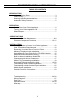
ENVIROFIRE INSTALLATION MANUAL TABLE OF CONTENTS INTRODUCTION Important Safety Data........................................................... 3 Pellet Quality ........................................................................ 4 Warnings and Recommendations......................................... 5 Automatic Safety Features ................................................... 5 OPERATION How to Start Your Pellet Appliance....................................... 6 Turning Your Pellet Appliance Off .....
IMPORTANT SAFETY DATA Please read this entire manual before installation and use of this pellet fuel burning room heater. Failure to follow these instructions could result in property damage, bodily injury or even death. CAUTION: DO NOT CONNECT OT ANY AIR DISTRIBUTION DUCT OR SYSTEM; DO NOT BURN GARBAGE OR FLAMABLE FLUIDS SUCH AS GASOLINE, NAPTHA OR ENGINE OIL; HOT WHILE IN OPERATION. KEEP CHILDREN, CLOTHING AND FURNITURE AWAY. CONTACT MAY CAUSE SKIN BURNS.
PELLET QUALITY IS IMPORTANT, PLEASE READ THE FOLLOWING PAGE Your pellet stove has been designed to burn wood pellets only. Since there are many manufacturers of wood pellets it is important to select pellets that are free of dirt or any impurities. The Pellet Fuel Industries (P.F.I.) has established standards for wood pellet manufactures. We recommend the use of pellets that meet or exceed these standards. Ask your dealer for a recommended pellet type.
WARNINGS AND RECOMMENDATIONS A. Do not abuse the glass by striking or slamming the door shut. B. Do not attempt to operate the stove with broken glass. C. Do not attempt to open the door and clean the glass while the unit is in operation. If you must clean the glass, use a soft cotton cloth and mild window cleaner. D. Do not use abrasive cleaners to clean the surface or any part of the stove. E. It is recommended that the unit be secured into its position in order to avoid any displacement. F.
HOW TO START AND OPERATE YOUR PELLET APPLIANCE 1. Check and fill hopper with pellets. 2. Switch on power by pushing the start up switch once only. 3. Turn the Dial A Fire knob to the 12 o’clock position. (Lower grade pellets may need a higher setting on the feed rate). NOTE: unit will take longer to light if the hopper has been completely emptied. 4. 5. 6 CONVECTION BLOWER SPEED CONTROL Wait until the fire is established, then turn knob “B” to the desired heat output.
SLIDER/DAMPER INSTALLATION /OPERATION INSTRUCTIONS This is used to regulate the airflow through the pellet stove. INSTALLATION 1. Remove the slider rod (short rod with knob and nuts) and the two nuts from their package and open the left side panel. 2. Remove the knob and outer nut from the knob. Push the rod through the hole in the slider. Place the lock nut on the rod and tighten, leaving a 1/32’ gap between the slider and one of the nuts. 3. Make sure the slider moves freely.
AREAS FOR ROUTINE INSPECTION The following should be inspected periodically to ensure that the appliance is operating at its optimum and giving you excellent heat value: 2-3 DAYS/WEEKLY Burn Pot and Liner Ash Pan Inside Firebox Behind Firebox Liners Door Glass Heat exchanger tubes Ash pan and Door gaskets SEASONALLY or 2 TONS OF FUEL Exhaust Vent and Fresh Air Intake Tube Blower Mechanisms Heat exchanger tubes Latch Mechanism of ash pan Door Latch All Hinges Post Season Clean-up TOOLS REQUIRED TO CLEAN UN
DOOR GLASS (It is recommended that your dealer replace the glass if broken.) The door glass is made of 5 mm thick, high temperature PYROCERAMIC The center panel is 229 mm x 330 mm. To replace the glass, unscrew and remove the four glass retainers. Remove the glass and any broken pieces. High temperature fiberglass tape should be used around the glass. Replace the glass, center the glass assembly in the frame, then screw the glass retainers back to the frame. The use of substitute materials is prohibited.
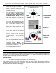
ELECTRICAL COMPONENT FUNCTIONS The following is a list of electrical components and their functions on the ENVIROFIRE EF-IIIi Bay pellet stove. 1. CONVECTION FAN CONTROLLER This controller is responsible for varying the speed of the convection blower. The stove does have a fan control over-ride. Should the convection blower be set on low and dial-a-fire set on high, the convection blower will bypass the fan controller and go to high.
. 160°F (71°C) TEMPERATURE SENSOR When this sensor (located on the left side firewall) reaches 160°F (71°C), the convection blower will go to high, cooling the unit. 12. 140°F (60°C) N/O TEMPERATURE SENSOR (SHUT-DOWN SENSOR) This sensor (mounted on the exhaust blower housing) has two functions: Should the fire go out, this sensor will shut the stove off when the exhaust temperature drops below 140°F (60°C).
DECIDING WHERE TO LOCATE YOUR PELLET APPLIANCE 1. Check clearances to combustibles. 2. Do not obtain combustion air from an attic, garage or any unventilated space. Combustion air may be obtained from a ventilated crawlspace. 3. Do not install the stove in a bedroom. 4. You can vent the stove through an exterior wall behind the unit or connect it to an existing masonry or metal chimney (must be lined if the chimney is over 6” in diameter, or over 28 sq. inches cross sectional area).
REMOVING YOUR NEW STOVE FROM IT’S PALLET To remove your new stove from its pallet, open the left and right side panels. There are two wood screws that are holding the bottom of the stove to the pallet. Remove the screws. Close the side panels. See PAGE 18 how to install the pedestal. INSERT MODEL FREE STAND MODEL REMOVE SCREW HERE FIREPLACE DIMENSIONS 24” 30.
MASONRY FIREPLACE INSERT INSTALLATION, MODEL FPI The Fireplace Insert model includes surround face plates and a pedestal. When installing this unit, ensure that the pedestal is removed from its box and installed on the bottom of the unit. (Surround assembly instructions are in this manual). CLEARANCE TO COMBUSTIBLES: Side wall............................................8” (200 mm) from the body of the heater Facing on masonry fireplace.............8” (200 mm) from the body of the heater Mantle .............
ASSEMBLING THE FACE PLATE FOR THE FPI AND BIH MODELS 1. To attach the pedestal, place the unit on its back, making sure not to damage the wiring, then bolt the pedestal onto the unit. Back off the screws on the base, install the pedestal over the screws. Lock in place using the keyholes, tighten the screws. 2. Assemble the three faceplates to the stove by screwing the hinged panels to the stove side panels. Loosen the front hopper lid screws and center the top panel under the hopper lid, tighten screws.
RECOMMENDED FRAMING FOR BUILT IN HEATER When installing model BIH it is recommended that you use the dimensions shown in the diagram below. These type of clearances will make it easy and readily accessible for service. BUILT IN HEATER CLEARANCES TO COMBUSTIBLES This unit includes a 3” (75 mm) pedestal and surrounding faceplates. The part of the unit behind the faceplate can be enclosed with combustible material.
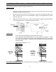
FREESTANDING INSTALLATION, MODELS FS CLEARANCES TO COMBUSTIBLES (FREESTANDING) - Side wall to unit A- 6 INCHES (150 mm) - Back wall to unit B- 1 INCH (25 mm) - Corner to unit C- 1 INCH (25 mm) - Mantle (Hearth Mount) 8 INCHES ( - Combustible flooring underneath the unit and extending 6 INCHES (150 mm) to the sides and front must be protected by a non combustible material. ALCOVE DIMENSIONS Minimum Alcove width...........36 inches (900 mm) Minimum Alcove height .........
MODEL FS (FREESTANDING) INSTALLATION PEDESTAL INSTALLATION: Model FS comes with a pedestal that has to be attached prior to installation: - Remove the pedestal from the box Remove the ENVIROFIRE heater form the box. Place the unit on its back, making sure not to damage the wiring. Back off the screws on the base, install the pedestal over the screws. Lock pedestal in place using the keyholes, tighten the screws. Return unit to upright.
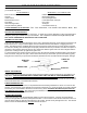
HORIZONTAL EXHAUST THROUGH THE WALL 1. NOTE: Use only listed type “PL” or “L” pellet venting products. Failure to use listed components may cause damage or personal injury or death. 2. Choose a location for your stove that meets the requirements stated in this manual and allows installation with the least amount of interference to house framing, plumbing, wiring, etc. 3. Install a non-combustible hearth pad underneath the unit extending 6 inches (15 cm) in front of and to the sides. 4.
THROUGH WALL INSTALLATION 1” 20
FREESTANDING INSIDE VERTICAL INSTALLATION 1. Choose a stove location that is ideal. See the section Deciding Where to Locate Your Pellet Appliance. 2. Place a non-combustible hearth pad where necessary. 3. Place the unit on the hearth pad and space it in a manner so when the pellet vent is installed vertically, it will be 3” (76 mm) away from a combustible wall. 4. Locate the center of the fresh air intake pipe on the unit.
FREESTANDING OUTSIDE VERTICAL INSTALLATION To accomplish the above titled installation, follow steps 1 through 8 in the previous section and then finish it by performing the following. 9. Install a tee with clean out on the outside of the house. 10. Install PL vent upward from the tee. Make sure that you install support brackets to keep the vent straight and secure. 11. Secure the flashing as you go through the roof. 12. Ensure that the rain cap is approximately 36” (900 mm) above the roof.
MOBILE HOME INSTALLATION - Secure the heater to the floor using the two bolt holes supplied in the pedestal. - CAUTION: THE STUCTURAL INTEGRITY OF THE MANUFACTURED HOME FLOOR, WALL, AND CEILING/ROOF MUST BE MAINTAINED. - Ensure the unit is electrically grounded to the chassis of your home (permanently). - Do not install in a room people sleep in. - Outside fresh air is mandatory when installing into airtight homes or manufactured homes.
TROUBLESHOOTING DO NOT: - Hold the start-up switch down, this is a momentary contact switch and can be damaged if held down too long. - Service the stove with wet hands. The stove is an electrical appliance, which may pose a shock hazard if handled improperly. Only qualified technicians should deal with possible internal electrical failures. - Remove any screws in the firebox without first lubricating them with penetrating oil. TROUBLESHOOTING: What to do if: 1. 2. 3. 4. 5. 6. 7. 8. 9.
4. The convection blower will not function normally - 5. Check all the connections between the controller, switch, and the convection blower against the wiring diagram. If the convection motor will not run, apply 115 V to the motor directly. If the motor runs, replace the fan controller. If the motor does not run, the convection blower has failed. Replace the blower.
7. placing a jumper across the pins. If the auger now cycles very quickly, test the dial-a-fire potentiometer. If the auger did not cycle then replace the timing control module. To test the dial-a-fire potentiometer. The potentiometer should have a range of 68K to approximately 850 K (± 10%), if the range is not close then replace the potentiometer. The dial-a-fire has no effect on the fire - Make sure all connections to the timer control module are secure.
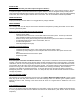
WIRING DIAGRAM 27
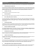
PARTS LIST EF-001 EF-002 EF-004 EF-007 EF-008 EF-009 EF-010 EF-011 EF-012 EF-013 EF-015 EF-016 EF-017 EF-018 EF-021 EF-024 EF-025 EF-026 EF-028 EF-029 EF-036 EF-037 EF-041 EF-043 EF-044 EF-045 EF-047 EF-050 EF-051 EF-054 EF-055 EF-056 EF-062 EF-064 EF-065 EF-066 EF-067 EF-068 EF-069 EF-070 EF-071 EF-071A EF-073 EF-074 EF-074A EF-076 EF-077A EF-078 EF-079 AUGER MOTOR CONVECTION BLOWER CONVECTION BLOWER IMPELLER COMBUSTION BLOWER COMPLETE COMBUSTION MAIN IMPELLER COMBUSTION COOLING IMPELLER EXHAUST TEMP SENS
AUGER BRASS BUSHING SET OF TWO FAN TEMP SENSOR 160°F (71°C) EF-065 EXHAUST TEMP SENSOR 140°F (60°C) EF-013 PIN IGNITER EF-127 EF-010 COMBUSTION BLOWER COMPLETE EF-007 HIGH LIMIT SENSOR 200°F (93°C) MANUAL RESET EF-016 CONVECTION BLOWER EF-002 IGNITER TEMP SENSOR 120°F (49°C) VACUUM SWITCH EF-017 EF-015 AUGER EF-025 FAN CONTROLLER EF-045 AUGER MOTOR EF-001 GREEN LIGHT AUGER BRASS BUSHING AND PLATE EF-041 EF-026 IEC POWER OUTLET CONTROL PANEL W/ DECAL EF-053 START SWITCH EF-043 AU
FPI OVERSIZED SURROUND BIH OVERSIZE SURROUND EF-078 EF-079 EF 2/3 HOPPER LID WITH HANDLE CONTROL PANEL W/DECAL EF-104 EF3Bi DECORATIVE TRIVET EF-150 PAINTED EF-151 GOLD EF-053 EF 3Bi STOVE TOP EF3Bi FS HOPPER SIDE RAIL EF-111 EF-143 HOPPER LID HINGE EF-141 EF3Bi FPI SIDE RAILS (R & L) EF 3Bi FPI STOVE TOP EF-145 EF-114 EF3Bi FS RIGHT CABINET SIDE EF-133 EF3Bi FPI HINGED CABINET SIDE (R & L) ASH PAN COVER MAGNETS EF3Bi FPI BIH HOPPER LID EF-131 EF-122 EF3Bi FIREBOX LINER W/ INSULATION
WARRANTY Sherwood Industries Ltd. gives a five year limited warranty on all steel manufactured parts. A one year warranty is provided on all electrical components. The above limited warranties are extended only to the original purchaser. There is no warranty on the following parts: - Glass window Fiberglass rope baskets Refractory material Burn pot liner Paint Enamel finish or gold plating where it applies, and, Vacuum hose.