SHERWOOD INDUSTRIES IS AN ENVIRONMENTALLY RESPONSIBLE COMPANY. THIS MANUAL IS PRINTED ON RECYCLED PAPER. PLEASE KEEP THESE INSTRUCTIONS FOR FUTURE REFERENCE PELLET STOVE EF3 Freestanding, Fireplace Insert, and Built-In Heater OWNER’S MANUAL Contact your building or fire officials about restrictions and installation inspection requirements in your area. PLEASE READ THIS ENTIRE MANUAL BEFORE INSTALLATION AND USE OF THIS PELLET BURNING ROOM HEATER.
Table of Contents Introduction...................................................................................................................................3 Pellet Quality........................................................................................................................3 Rating Label Location...........................................................................................................3 Important Safety Data..............................................................
Introduction PELLET QUALITY: Pellet quality is important, please read the following: Your enviro pellet stove has been designed to burn wood pellets only. Do not use any other type of fuel, as this will void any warranties stated in this manual. The performance of your pellet stove is greatly affected by the type and quality of wood pellets being burned. As the heat output of various quality wood pellets differs, so will the performance and heat output of the pellet stove.
Introduction IMPORTANT SAFETY DATA: Please read this entire Owner’s Manual before installing or operating your ENVIRO Pellet Stove. Failure to follow these instructions may result in property damage, bodily injury or even death. Contact your local building or fire official to obtain a permit and any information on installation restrictions and inspection requirements for your area.
Introduction ASHES: Disposed ashes should be placed in a metal container with a tight fitting lid. The closed container of ashes should be on a non-combustible floor on the ground, well away from all combustible materials pending final disposal. If the ashes are disposed of by burial in soil or otherwise locally dispensed, they should be retained in the closed container until all cinders have been thoroughly cooled. ELECTRICAL: The use of a surge protected power bar is recommended.
Operating Instructions AUTOMATIC SAFETY FEATURES: Your pellet Stove has the following safety features: A. The stove will shut off when the fire goes out and the exhaust temperature drops below 120°F (49°C). B. The stove has a high temperature safety switch. If the temperature on the hopper reaches 200°F (93°C), the auger will automatically stop and the stove will shut down when the exhaust temperature cools. If this happens, call your local dealer to reset the 200°F (93°C) high limit switch.
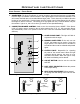
Operating Instructions STOVE CONTROLS - CIRCUIT BOARD: 1. AUGER TRIM: The Auger Trim Button is used to increase or decrease the feed rate on LOW, ONLY. Push the Auger Trim button until the number 1 and 5 lights appear on the Heat Level Indicator. This will increase the feed rate to 4 seconds ON time Auger pulse. This is done only on LOW to allow the burning of poor quality fuels. Push the button until the number 1 and 4 lights appear, this will reduce the Auger On time to 2 second.
Operating Instructions OPERATING YOUR PELLET STOVE - CIRCUIT BOARD: PRE-BURN INSTRUCTIONS: The burn pot liner holes must be clear and the liner installed properly against the ignitor tube for proper operation. Check the hopper for enough pellets to start the unit. DO NOT OPERATE THE UNIT WITH THE DOOR OR ASH PAN AJAR MANUAL MODE: TO START: Press the ON / OFF button. The stove will turn on. The system light will flash.
Operating Instructions OPERATING YOUR PELLET STOVE - TIMER CONTROL: 1. Check and fill hopper with pellets. 2. Make sure unit is plugged into a working outlet. 3. Switch the power “ON” by pushing the start-up switch once only. 4. Turn knob “B” to the 12 o’clock position. (Lower grade pellets may need a higher setting on the feed rate). NOTE: Unit will take longer to light if the hopper has been completely emptied or is the first fire up. 5.
Routine Cleaning and Maintenance NOTE: Do not use abrasive cleaners to clean the surface or any part of the stove.
Routine Cleaning and Maintenance ASH PAN (2-3 days) Monitor the ash level every week. Remember that different pellet fuels will have different ash contents. Ash content is a good indication of fuel efficiency and quality. Refer to “Warnings and Recommendations” for disposal of ashes. DO NOT PLACE UNBURNED OR RAW PELLET FUEL IN ASH PAN. Dump the ashes into a metal container stored away from combustibles. Monitor the ash level every week. Remember that different pellet fuels will have different ash contents.
Routine Cleaning and Maintenance Installation of firebox backing: • Install the side panels in place. Insert center panel, hold the panels in place • Install the top rod by sliding it into one side panel then across into the other panel. Screw rod in place. • Re-install steel brick liner and screw in place. • Replace top baffle EXHAUST VENT (season) The products of combustion will contain small particles of flyash.
Installation DECIDING WHERE TO LOCATE YOUR PELLET APPLIANCE: 1. Check clearances to combustibles. 2. Do not obtain combustion air from an attic, garage or any unventilated space. Combustion air may be obtained from a ventilated crawlspace. 3. Do not install the stove in a bedroom. 4.
Installation DIMENSIONS - FREESTANDING: �� ������ ���� ��� �� ���� ���� ��� �� ���� ���� ��� ��� ���� ��� �� ������ ���� ��� Figure 8: Dimensions of EF3 Freestanding. DIMENSIONS - FIREPLACE INSERT AND BUILT-IN HEATER: �� ���� ���� ��� �� ������ ���� ��� �� ������ ���� ��� ������ �� ������ ���� ��� �������� �� ���� ���� ��� Figure 9: Dimensions of EF3 Fireplace Insert.
Installation CLEARANCES TO COMBUSTIBLES - FREESTANDING: When installing this unit on a combustible floor (for example linoleum, hardwood flooring) a noncombustible hearth pad must be under the unit. The pad must extend at least the width of the appliance [22” (558 mm)] and at least the depth of the appliance plus 6” (153 mm) in front of the appliance [29 3⁄4” (756 mm)]. Side wall to unit -6 Back wall to unit -1 Corner to unit -1 Door front to edge of floor -6 inches (15 cm) inches (2.5 cm) inches (2.
Installation CLEARANCES TO COMBUSTIBLES - BUILT-IN HEATER: Refer to Figures 12 and 13. 33" (84 cm) Side wall to unit - 8 inches (20.3 cm) Mantel projection - 10 inches (25.4 cm) Mantel to top of unit - 8 inches (20.3 cm) Top facing to unit - 8 inches (20.3 cm) Side facing to unit - 6 inches (15.2 cm) Floor protection - 6 inches (15.
Installation VENT TERMINATION REQUIREMENTS: IT IS RECOMMENDED THAT YOUR PELLET STOVE BE INSTALLED BY AN AUTHORIZED DEALER/INSTALLER. Table 1: Use in conjunction with Figure 17 for allowable exterior vent termination locations. Letter Minimum Clearance A 24 in (61 cm) Description Above grass, top of plants, wood, or any other combustible materials. B 48 in (122 cm) C 24 in (61 cm) From beside/below any door or window that may be opened. From above any door or window that may be opened.
Installation OUTSIDE FRESH-AIR CONNECTION: Outside fresh air is mandatory when installing this unit in airtight homes and mobile homes. ������� ���� When connecting to an outside fresh air source, do not use plastic or combustible pipe. A 15⁄8” minimum (42 mm) ID (inside diameter) steel, aluminum or copper pipe should be used. It is recommended, when you are installing a fresh air system, to keep the number of bends in the pipe to a minimum.
Installation MOBILE HOME INSTALLATION - FREESTANDING: ● Secure the heater to the floor using the two (2) holes in the pedestal. ● Ensure the unit is electrically grounded to the chassis of your home (permanently). ● Do not install in a room people sleep in. ● Outside fresh air is mandatory. Secure outside air connections directly to fresh air intake pipe and secure with three (3) screws evenly spaced.
Installation HORIZONTAL EXHAUST THROUGH WALL INSTALLATION - FREESTANDING: Vent installation: install vent at clearances specified by the vent manufacturer. A chimney connector shall not pass through an attic or roof space, closet or similar concealed spaces, or a floor, or ceiling. Where passage through a wall or partition of combustible construction is desired, the installation shall conform to CAN/CSA-B365 Installation Code for Solid-Fuel-Burning Appliances and Equipment.
Installation 10. The pipe must extend at least 12” (30 cm) away from the building. If necessary, bring another length of pipe (PL type) to the outside of the home to connect to the first section. Do not forget to place high temperature silicone around the pipe that passes through the thimble. 11. Install a vertical pipe, or if all requirements for direct venting are met, install vent termination. The stainless steel cap termination manufactured by the vent manufacturer is recommended.
Installation INSIDE VERTICAL INSTALLATIONS - FREESTANDING: 1. Choose a stove location that is ideal. See the section “DECIDING WHERE 2. Place a non-combustible hearth pad where necessary. 3. Place the unit on the hearth pad (if installed on a carpeted surface) and space the unit in a manner so when the pellet vent is installed vertically, it will be 3” (7.6 cm) away from a combustible wall. 4. Locate the center of the fresh air intake pipe on the unit.
Installation Rain cap Flashing 24" (61 cm) 3" (7.5 cm) Clearance 2" (5 cm) ���� ��� Support bracket ��������� ������ Tee with cleanout ����� ����� �� �������� �������� �� ����� �� ��������� ����� ����� 6" (15 cm) Type "L" vent Fresh air intake Non-combustible floor protection. Existing floor (combustible) Figure 28: Outside Vertical Installation.
Installation ���� ��� ����� ������ ���� ����� ������ ������ �������� ������� ���� ���� ���� ������� ���� ��������� ���� ���� �� ����� �� ����� �������� ���� ��������� ���� ���� � ���� ������� ������� �� ���� �� ���� ���� ��������� ������ �� ����� ����� � ��������� ������ �������� ����� ��� ��� �������� ��������� ������ ��� Figure 30: Freestanding hearth mount installation overview. MASONRY FIREPLACE INSTALLATION - FIREPLACE INSERT: The fireplace insert model requires a surround panel and a pedestal.
Installation ���� ��� ��������� ������ ����� ����� �� �������� �������� �� ����� �� ��������� ����� ����� ������ ������� �� �������� ���� �������� ��������� ����� ���� ���������� ������ ������� �� ��� ��� ���� ��� �� ����� 4. Connect a tee or 90° degree elbow to the exhaust pipe. 5. This fireplace insert must be installed with a continuous chimney liner of 3” or 4” diameter extending from the fireplace insert to the top of the chimney. The liner must conform to type 3 requirements of CAN/ULC S635. 6.
Installation INSTALLATION FOR A BUILT-IN HEATER: This unit includes a 3” (75 mm) pedestal and surrounding faceplates. The part of the unit behind the faceplate can be enclosed with combustible material. It has 1” (25 mm) standoffs to establish clearances to combustibles to the back, top and sides. Combustible materials and structure Surround Panel Wall thimble 12" (30.
Installation INSTALLATION AND REMOVAL OF THE SURROUND PANELS - FPI AND BIH: Corner Brackets Two (2) pieces make up one (1) corner bracket Magnetic Strips Figure 36: Assembling Trim for Surround Panel. 1. Assemble the trim set using the corner hardware and screws supplied in the surround panel packaging. Install corner hardware into the side trim pieces, then push them into the top trim. Do not over-tighten the corners or the side trim cannot be removed during servicing. See Figure 36. 2.
Installation REMOVAL: When maintenance is required on the unit the surround must be removed. Follow steps 3 through 6 in reverse order. The side panel can remain attached because they swing forward for easy access (refer to Figure 37). ���� ��������� ����� ��� Figure 39: Side surround panel swings forward. SLIDER/DAMPER INSTALLATION: This is used to regulate the airflow through the pellet stove. 1. Remove the slider rod (short rod with knob and nuts) from their package and open the left side panel. 2.
Troubleshooting This troubleshooting is for both Timer Control and Circuit Board style EF3. It will be stated if the troubleshooting relates only to one model. DO NOT: ● Hold the ON / OFF BUTTON down for circuit board model or hold the start-up switch down for timer control. This is a momentary contact switch and can be damaged if held down too long. ● Service the stove with wet hands. The stove is an electrical appliance, which may pose a shock hazard if handled improperly.
Troubleshooting Caution: Installation of a new start-up timer without checking the ignitor resistance may cause another failure to the new start-up timer due to a short in the ignitor. The proper resistance through the ignitor should be 30Ω to 50Ω ± 3Ω. 2. The stove will not operate when hot. General: ● Check the hopper for fuel. ● Incorrect air damper setting - Excessive air may consume the fire too quickly before the next drop of fuel, leaving completely unburned fuel in the burn pot liner.
Troubleshooting ● Check all the connections between the controller, switch, and the convection blower against the wiring diagram. ● If the convection motor will not run, apply 115 V AC to the motor directly. If the motor runs, replace the fan controller. If the motor does not run, the convection blower has failed. Replace the blower.
Troubleshooting ● To test the exhaust vacuum, place a magnehelic gauge in the sensor end of the vacuum tube. It should read 0.5” W.C. If the reading is good, replace the vacuum sensor. ● If none of the below work contact your local dealer for service. Circuit Board □ Check the fuses on the circuit board (see “Troubleshooting - Fuses”). Timer Control: ◊ Make sure the dial-a-fire is turned on. ◊ Unplug the stove and open the side and back panels.
Troubleshooting 10. The stove will not shut off. General: ● If the unit will not shut off, ensure that the thermostat (if equipped) is turned down below the room temperature (thermostat mode in the ON / OFF position). ● Disconnect one of the brown wires from the exhaust temperature sensor. If the unit continues to operate, contact your local dealer for service. Circuit Board: □ If the unit is in the HI/LOW mode the unit will not shut off but will go to an idle setting (LOW).
Troubleshooting If the stove goes out and there are no pellets in the liner, the auger is stopping. General: ● See “The auger motor will not function normally” and “The exhaust blower will not function normally.” 12. Light # 2 on Heat output bar flashing (Circuit Board Only). (The Vacuum Switch contacts have opened for more than 15 sec.) □ Pinch, break or blockage in Vacuum Hose - Check hose for pinch points or damage, replace or re-route as required.
Wiring Diagram CIRCUIT BOARD: Grey Vacuum Switch Grey Blue Combustion Blower White Brown 120oF Power Cord (49oC) Exhaust Temperature Sensor Brown Black Black Red White Ignitor Black 200oF (93oC) High Limit Temperature Sensor White Black Common Hot 5 Amp Fuses Thermostat 5 V DC Black White Purple White Auger Motor J2 Black 160oF (71oC) Convection Blower Sensor Convection Blower Ground Yellow White Orange Orange Orange Orange Purple Blue Yellow Red Grey Grey Brown Brown Red Connec
Wiring Diagram TIMER CONTROL: 160oF (71oC) Convection Temperature Sensor Purple Purple 140oF (60oC) Exhaust Temperature Sensor Vacuum Switch Exhaust/Combustion Blower Brown Brown Blue Blue Brown Brown Purple Black Power Cord Brown Brown Ignitor 120oF (49oC) Ignitor Temperature Sensor Orange Blue Orange Grey Auger Motor Auger Timer Convection Blower Brown White Black Black Purple Purple Purple Yellow Yellow Dial-A-Fire Black Grey Blue Grey Purple Start-Up Timer Brown Black Brown White Whit
Parts List Reference Number Description Part Number 1 Exhaust Temperature Sensor 120°F (60°C) [Circuit Board] EC-001 1 Exhaust Temperature Sensor 140°F (60°C) Ceramic [Timer Control] EF-010 Freestanding Fan Controller Knob EC-040 Power Cord - 115V EC-042 2 Auger Motor - 115V EF-001 3 Convection Blower - 115V EF-002 Convection Blower Impeller EF-004 Convection Blower Insulator (Gasket) EF-006 Combustion Main Impeller EF-008 Combustion Cooling Impeller EF-009 Combustion Blower Mount
Parts List Reference Number Part Number Firebox Liner Top Plate EF-066 Dial-a-Fire Knob [Timer Control] EF-067 3⁄4” ID Auger Collar with Set Screw EF-069 Knob 1 Inch Round EF-070 Wiring Harness [Timer Control] EF-071 Fireplace Insert Pedestal Complete EF-074 Built-In Heater Pedestal EF-074A Freestanding Back Grill EF-097 Freestanding Ash Pan Cover EF-099 Built-In Heater Kit EF-102 23 Freestanding Hopper Lid With Handle EF-104 24 Fireplace Insert Ash Pan Drawer With Latch EF-105 2
Parts List Reference Number Description Part Number Circuit Board Decal [Circuit Board] 50-179 44 Control Panel Touch Latch 50-323 45 Combustion Blower Exhaust Tube 50-327 46 Circuit Board Control Panel [Circuit Board] 50-330 47 Stainless Steel Burn Pot Liner - Domestic 50-474 47 Stainless Steel Burn Pot Liner - High Ash 50-587 Convection Blower Mount 50-524 Firebox Liner Top Rod 50-591 48 Door Assembly 50-602 49 Door Hinge Bracket 50-604 50 Freestanding Phase Control Panel Co
Parts Diagram - Components �� �� �� �� �� �� �� � �� �� � �� � �� �� �� � December 2004 �� EF3 - Components (115V) � � �� � �� � 40
�� December 2004 �� �� �� �� EF3 - Steel Components (220V) �� �� �� �� �� �� �� �� �� �� �� �� �� �� �� �� �� � �� �� �� �� �� �� �� �� �� �� �� �� �� �� Parts Diagram - Steel 41
Warranty Sherwood Industries Ltd. gives a five year limited warranty on all steel manufactured parts. A one-year warranty is provided on all electrical components. The above limited warranties are extended only to the original purchaser. There is no warranty on the following parts: ● Glass window ● Fiberglass rope gaskets ● refractory material ● burn pot liner ● paint ● enamel finish or gold plating where it applies **NOTE: The paint on the brick firebox lining may peel.
Installation Data Sheet The following information must be recorded by the installer for warranty purposes and future reference.