SHERWOOD INDUSTRIES IS AN ENVIRONMENTALLY RESPONSIBLE COMPANY. THIS MANUAL IS PRINTED ON RECYCLED PAPER. PLEASE KEEP THESE INSTRUCTIONS FOR FUTURE REFERENCE PELLET STOVE EF3 Freestanding, Fireplace Insert, and Built-In Heater OWNER’S & TECHNICAL MANUAL Contact your building or fire officials about restrictions and installation inspection requirements in your area. PLEASE READ THIS ENTIRE MANUAL BEFORE INSTALLATION AND USE OF THIS PELLET BURNING ROOM HEATER.
Table of Contents Introduction...................................................................................................................................3 Pellet Quality........................................................................................................................3 Rating Label Location...........................................................................................................3 Important Safety Data..............................................................
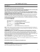
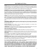
Introduction Pellet Quality: Pellet quality is important, please read the following: Your enviro pellet stove has been designed to burn wood pellets only. Do not use any other type of fuel, as this will void any warranties stated in this manual. The performance of your pellet stove is greatly affected by the type and quality of wood pellets being burned. As the heat output of various quality wood pellets differs, so will the performance and heat output of the pellet stove.
Introduction Important Safety Data: Please read this entire Owner’s Manual before installing or operating your ENVIRO Pellet Stove. Failure to follow these instructions may result in property damage, bodily injury or even death. Contact your local building or fire official to obtain a permit and any information on installation restrictions and inspection requirements for your area.
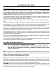
Introduction ASHES: Disposed ashes should be placed in a metal container with a tight fitting lid. The closed container of ashes should be on a non-combustible floor on the ground, well away from all combustible materials pending final disposal. If the ashes are disposed of by burial in soil or otherwise locally dispensed, they should be retained in the closed container until all cinders have been thoroughly cooled. ELECTRICAL: The use of a surge protected power bar is recommended.
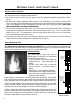
Operating Instructions Automatic Safety Features: Your pellet Stove has the following safety features: A. The stove will shut off when the fire goes out and the exhaust temperature drops below 120°F (49°C). B. The stove has a high temperature safety switch. If the temperature on the hopper reaches 200°F (93°C), the auger will automatically stop and the stove will shut down when the exhaust temperature cools. If this happens, call your local dealer to reset the 200°F (93°C) high limit switch.
Operating Instructions Operating Your Pellet Stove: 1. Check and fill hopper with pellets. 2. Make sure unit is plugged into a working outlet. 3. Switch the power “ON” by pushing the start-up switch once only. 4. Turn knob “B” to the 12 o’clock position. (Lower grade pellets may need a higher setting on the feed rate). NOTE: Unit will take longer to light if the hopper has been completely emptied or is the first fire up. 5. Wait until the fire is established, then turn “Knob B” to the desired heat output.
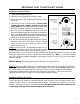
Routine Cleaning and Maintenance NOTE: Do not use abrasive cleaners to clean the surface or any part of the stove.
Routine Cleaning and Maintenance ASH PAN (2-3 days) Monitor the ash level every week. Remember that different pellet fuels will have different ash contents. Ash content is a good indication of fuel efficiency and quality. Refer to “Warnings and Recommendations” for disposal of ashes. DO NOT PLACE UNBURNED OR RAW PELLET FUEL IN ASH PAN. Dump the ashes into a metal container stored away from combustibles. Monitor the ash level every week. Remember that different pellet fuels will have different ash contents.
Routine Cleaning and Maintenance Installation of firebox backing: • Install the side panels in place. Insert center panel, hold the panels in place • Install the top rod by sliding it into one side panel then across into the other panel. Screw rod in place. • Re-install steel brick liner and screw in place. • Replace top baffle EXHAUST VENT (season) The products of combustion will contain small particles of flyash.
Installation Deciding Where to Locate your Pellet Appliance: 1. Check clearances to combustibles. 2. Do not obtain combustion air from an attic, garage or any unventilated space. Combustion air may be obtained from a ventilated crawlspace. 3. Do not install the stove in a bedroom. 4.
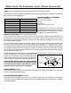
Installation Dimensions - Freestanding: 21 15/16" (557 mm) 23 3/4" (603 mm) 30 1/4" (768 mm) 22" (559 mm) 20 15/16" (532 mm) Figure 7: Dimensions of EF3 Freestanding. Dimensions - Fireplace Insert and Built-In Heater: 23 5/8" (600 mm) 21 15/16" (557 mm) 12 11/16" (322 mm) Insert 22 15/16" (582 mm) Built-In 24 5/8" (626 mm) Figure 8: Dimensions of EF3 Fireplace Insert.
Installation Clearances to Combustibles - Freestanding: When installing this unit on a combustible floor (for example linoleum, hardwood flooring) a noncombustible hearth pad must be under the unit. The pad must extend at least the width of the appliance [22” (558 mm)] and at least the depth of the appliance plus 6” (153 mm) in front of the appliance [29 ¾” (756 mm)]. Side wall to unit -6 Back wall to unit -1 Corner to unit -1 Door front to edge of floor -6 inches (15 cm) inches (2.5 cm) inches (2.
Installation Clearances to Combustibles - Built-In Heater: Refer to Figures 11 and 12. Side wall to unit - 8 inches (20.3 cm) Mantel projection - 10 inches (25.4 cm) Mantel to top of unit - 8 inches (20.3 cm) Top facing to unit - 8 inches (20.3 cm) Side facing to unit - 6 inches (15.
Installation Vent Termination Requirements: IT IS RECOMMENDED THAT YOUR PELLET STOVE BE INSTALLED BY AN AUTHORIZED DEALER/INSTALLER. Table 1: Use in conjunction with Figure 16 for allowable exterior vent termination locations. Letter Minimum Clearance A 24 in (61 cm) Description B 48 in (122 cm) Beside/below any door or window that may be opened. (18” (46 cm) if outside fresh air installed.) C 12 in (30 cm) Above any door or window that may be opened. (9” (23 cm) if outside fresh air installed.
Installation Outside Fresh-Air Connection: A Fresh-air intake is strongly recommended for all installations. Failure to install intake air may result in improper combustion as well as the unit smoking during power failures. Outside Wall The inlet to the intake must be below and a minimum of 12” (30cm) away from the unit exhaust outlet. Outside fresh air is mandatory when installing this unit in airtight homes and mobile homes.
Installation Mobile Home Installation - Freestanding: ● Secure the heater to the floor using the two (2) holes in the pedestal. ● Ensure the unit is electrically grounded to the chassis of your home (permanently). ● Do not install in a room people sleep in. ● Outside fresh air is mandatory. Secure outside air connections directly to fresh air intake pipe and secure with three (3) screws evenly spaced.
Installation Horizontal Exhaust Through Wall Installation - Freestanding: Vent installation: install vent at clearances specified by the vent manufacturer. A chimney connector shall not pass through an attic or roof space, closet or similar concealed spaces, or a floor, or ceiling. Where passage through a wall or partition of combustible construction is desired, the installation shall conform to CAN/CSA-B365 Installation Code for Solid-Fuel-Burning Appliances and Equipment.
Installation 10. The pipe must extend at least 12” (30 cm) away from the building. If necessary, bring another length of pipe (PL type) to the outside of the home to connect to the first section. Do not forget to place high temperature silicone around the pipe that passes through the thimble. 11. Install a vertical pipe, or if all requirements for direct venting are met, install vent termination. The stainless steel cap termination manufactured by the vent manufacturer is recommended.
Installation Inside Vertical Installations - Freestanding: 1. Choose a stove location that is ideal. See the section “Deciding Where 2. Place a non-combustible hearth pad where necessary. to Locate your Pellet Appliance.” Rain cap 3. Place the unit on the hearth pad (if installed on a carpeted surface) and space the unit in a manner so when the pellet vent is installed vertically, it will be 3” (7.6 cm) away from a combustible wall. Flashing 24" (61 cm) 3" (7.5 cm) clearance 4.
Installation Rain cap Flashing 24" (61cm) 3" (7.5cm) Clearance 1" (2.5cm) Rain Cap Support bracket Tee with cleanout Fresh-air intake Steel Plate or Flashing 6" (15cm) Type "L" vent Flexible or Rigid 6" Stainless Steel Liner Fresh air intake Non-combustible floor protection. Existing floor (combustible) Figure 27: Outside Vertical Installation. Hearth Mount Installation - Freestanding: Damper Removed or Fastened Open 10" (25.
Installation Rain cap Storm collar Seal plate (cover plate) Existing masonry flue Vent pipe (single wall stainless flex pipe or solid PL vent) Flexible vent connector (use this 5 foot [152cm] section of pipe to vent past fireplace damper or small shelf ) Fireplace damper location Clean out tee Existing fireplace ENVIRO EF3 Figure 29: Freestanding hearth mount installation overview. Masonry Fireplace Installation - Fireplace Insert: The fireplace insert model requires a surround panel and a pedestal.
Installation Rain Cap Fresh-air intake Steel Plate or Flashing Flexible or Rigid 6" Stainless Steel Liner Damper Removed or Fastened Open Flexible stainless steel pipe connection Mantel Minimum 8" (20 cm) from top of stove 4. Connect a tee or 90° degree elbow to the exhaust pipe. 5. This fireplace insert must be installed with a continuous chimney liner of 3” or 4” diameter extending from the fireplace insert to the top of the chimney. The liner must conform to type 3 requirements of CAN/ULC S635. 6.
Installation Installation For A Built-In Heater: Combustible materials and structure Surround Panel This unit includes a 3” (75 mm) pedestal and surrounding faceplates. The part of the unit behind the faceplate can be enclosed with combustible material. It has 1” (25 mm) standoffs to establish clearances to combustibles to the back, top and sides. Wall thimble 12" (30.5 cm) 45° elbow 6" (15 cm) Rodent mesh cap Fresh air intake Non-combustible floor protection. 3" (7.
Installation 4. Plug the wiring harness into the control panel (see Figure 33). 5. Loosen the front hopper lid screws and center the top surround panel under the hopper lid., tighten screws. 6. Insert each side panel anchor bolt through the top panel into the corresponding side panel holes and tighten using a 7/16” wench or socket (refer to Figure 38). Surround Panel 7. Place assembled trim over the surround assembly.
Installation The Tube Scraper Rod: Put the stainless steel rod through the hole in the heat exchanger located behind the top louvers. Thread the rod into the scraper plate, which is visible from inside the firebox by removing the top baffle. Figure 40: Tube scrapper rod placement. Slider/Damper Installation: This is used to regulate the airflow through the pellet stove. 1. Remove the slider rod (short rod with knob and nuts) from their package and open the left side panel. 2.
Troubleshooting DO NOT: ● Service the stove with wet hands. The stove is an electrical appliance, which may pose a shock hazard if handled improperly. Only qualified technicians should deal with possible internal electrical failures. ● Remove any screws in the firebox without first lubricating them with penetrating oil. WHAT TO DO IF: 1. The stove will not start. 2. The stove will not operate when hot. 3. The exhaust blower will not function normally. 4. The convection blower will not function normally. 5.
Troubleshooting ● Check Vacuum levels in the exhaust channel by bypassing the Vacuum Switch, then remove the Vacuum hose from Vacuum Switch. Check exhaust vacuum readings by placing the open end of the Vacuum Hose on a Magnehelic Gauge (readings must be above 0.10” W.C. on low fire). Note: If the motor fails to reach a 0.10” W.C. reading, then replace the Combustion Blower. ● Poor Quality Fuel – Insufficient energy in the fuel to produce enough heat to keep the stove burning or operational.
Troubleshooting 6. The auger motor will not function normally. ● If the Auger gear box does not turn but the motor’s armature does try to spin then the auger is jammed. – Try to break apart jam by poking at the jam through the drop tube. If this fails then empty the hopper and remove the Auger Cover **Remember to re-seal the cover after installation** ● Make sure the exhaust blower is operating. ● Check the condition of the vacuum hose (located on the left side of the stove).
Troubleshooting 8. The 200°F (93°C) high limit temperature sensor has tripped. ● Reset the sensor and determine the cause - was it convection blower or 160°F (71°C) temperature sensor failure? Bypass the 160°F (71°C) sensor. Does the convection blower come on high? If no, replace the blower. 9. The stove will not shut off. ● If the unit will not shut off, ensure that the thermostat (if equipped) is turned down below the room temperature (thermostat mode in the ON / OFF position).
Wiring Diagram 160oF (71oC) Convection Temperature Sensor Purple Purple 140oF (60oC) Exhaust Temperature Sensor Vacuum Switch Exhaust/Combustion Blower Brown Brown Blue Blue Brown Brown Purple Black Power Cord Brown Brown Ignitor 120oF (49oC) Ignitor Temperature Sensor Orange Blue Orange Grey Auger Motor Auger Timer Convection Blower Brown White Black Black 120 V Black 220 V Brown Purple Purple Purple Yellow Yellow Dial-A-Fire Black Grey Blue Grey Purple Start-Up Timer Brown 120 V White 2
Parts List Reference Number Description Freestanding Fan Controller Knob EC-040 Power Cord - 115V EC-042 Window Channel Tape 60” (1.
Parts List Reference Number 17 Description Part Number Freestanding Pedestal Complete EF-139 Ignitor Tube Only EF-140 Pellet Stove Cleaning Brush EF-156 18 Freestanding Ash Pan Latch EF-178 19 FPI & BIH Ash Pan Cover Magnet Set EF-188 20 Firebox Cleaning Port Covers 21 FPI & BIH Hopper Lid With Knob, Stud, and Hinge EF-202 Pedestal & Ash Pan Gasket 10’ (3 m) EF-208 Dial-a-Fire Control Panel Decal EF5-123 22 EF-194A Control Panel Door 20-040 ⅝” Door Gasket 7’ (2.
Parts List Reference Number Part Number 39 Fireplace Insert Ash Pan Drawer With Latch 50-1789 40 Freestanding Stove Top 50-1792 41 Fireplace Insert Stove Top 50-1794 EF3 Domestic Owner’s Manual 50-1795 42 Ash Sill 50-1796 43 FPI & BIH Hopper Cover 50-1797 44 Front Grill 50-1798 45 Steel Brick Lining 50-1799 46 Freestanding Right Cabinet Side 50-1800 47 Freestanding Left Cabinet Side 50-1801 48 Freestanding Hopper Lid Hinge 50-1802 49 Freestanding Hopper Side Rail (Left & R
23 11 12 14 13 2 28 6 30 2 5 52 10 9 29 EF3 - Components (115V) February 2008 4 34 33 7 24 3 1 Parts Diagram - Components 35
Parts Diagram - Steel 57 49 47 56 50 32 237 EF3 - Steel Components (115V) February 2008 55 43 38 21 27 17 39 51 19 53 15 25 41 16 40 48 8 18 49 50 46 31 36 45 20 54 42 44 26 35 36
Warranty Sherwood Industries Ltd. is the manufacturer of the Enviro line of heating products. At Sherwood Industries, our commitment to the highest level of quality and customer service is the most important thing we do. Each Enviro stove is built on a tradition of using only the finest materials and is backed by our Exclusive Lifetime Limited Warranty to the original purchaser. With Enviro, you’re not just buying a stove, you’re buying a company with years of unequalled performance and quality.
Warranty Exclusions and Limitations: 1. This Warranty does not cover tarnish, discoloration or wear on the plating or paint. 2. This Warranty excludes wear and tear or breakage caused by cleaning, moving or service on log set. 3. A qualified installer must install this stove or fireplace. This Limited Warranty covers defects in materials and workmanship only if the product has been installed in accordance with local building and fire codes; in their absence, refer to the owner’s manual.
Warranty 17. Damage to plated surfaces caused by fingerprints, scratches, melted items, or other external scores and residues left on the plated surfaces from the use of abrasive cleaners or polishes is not covered in this warranty. 18. The Limited Warranty does not cover tarnish, discoloration or wear on the plated surfaces. 19. The paint on the Metal Brick Liner may peel. This is due to the extreme conditions applied to the paint during normal usage. It is not a flaw and is not covered under warranty. 20.
Installation Data Sheet The following information must be recorded by the installer for warranty purposes and future reference.