FOR INSTALLERS AND SERVICE TECHNICIANS ONLY. PELLET STOVE SERVICE MANUAL Sherwood Industries Ltd. Duplication of this document is prohibited. All rights reserved.
Table of Contents Introduction......................................................................................................................................4 Stove Specifications...........................................................................................................................5 Stove Controls...................................................................................................................................8 Timer Control Panel:..................................
Table of Contents How To By-Pass The 200°F Manual Reset.....................................................................................34 How To Lubricate The Convection Blower.....................................................................................35 How To Remove The Convection Blower.......................................................................................35 How To By-Pass The 160°F Fan Sensor...................................................................................
Introduction This is a service guide designed by SHERWOOD INDUSTRIES LTD. We hope this manual will assist you to identify and correct operational concerns you might experience in all ENVIRO pellet stoves. This service guide is designed for SERVICE TECHNICIANS AND INSTALLERS ONLY, as a certain level of technical understanding is required. This guide is not designed for use by the homeowner.
3.9 Amp 3.9 Amp 4.5 Amp 4.5 Amp 4.7 Amp 4.7 Amp 4.1 Amp 4.6 Amp 4.1 Amp 5.0 Amp 4.7 Amp 4.7 Amp 5.0 Amp 6.0 Amp 6.0 Amp EF2i EF3Bi EF4i EF5-DIAL-A-FIRE EF5-CIRCUIT BOARD EMPRESS FS MERIDIAN MINI WINDSOR (50-511 kit) EMPRESS FPI MILAN FPI WINDSOR (50-994 kit) MAXX OMEGA AMPERAGE EF2 MODEL 720W 720W 575W 540W 540W 575W 500W 520W 500W 540W 540W 520W 520W 450W 450W WATTAGE 850W 850W 600W 600W 600W 600W 600W 600W 600W 600W 600W 600W 600W 600W RECOMMENDED Min.
Stove Specifications EMPRESS FPI MINI MERIDIAN EMPRESS FS EF5-CIRCUIT BOARD EF5-DIAL-A-FIRE EF4i EF3Bi EF2i EF2 76V 76V 76V 76V 76V 76V 69V 69V Line V Line V 1 Line V 93V 83V 83V 83V 83V 83V 83V 103V 99V 90V 90V 90V 90V 90V 90V VARIABLE VARIABLE 108V 104V 97V 97V 97V 97V 97V 97V Line V Line V Line V Line V Line V Line V Line V Line V Line V Line V Line V Line V Line V Line V Line V Line V Line V Line V 87V 0 79V 64V 82V 78V 75V 80V 69V 69V
Stove Specifications MODEL HEAT LEVEL (Green lite to Green lite) EF2/3 Low Blue 15.3 - 16.4 12.3 - 13.4 3.0 High Red 4.2 - 4.4 1.2 - 1.4 3.0 1 2 3 4 5 11.5 8.5 3.0 9.06 6.06 3.0 7.07 4.07 3.0 5.09 2.09 3.0 4.07 1.07 3.0 70,000 BTU 1 2 3 4 5 21.0 18.0 3.0 12.0 9.0 3.0 8.0 5.0 3.0 5.5 2.5 3.0 4.5 1.5 3.0 60,000 BTU 1 2 3 4 5 22.0 19.0 3.0 12.0 9.0 3.0 8.0 5.0 3.0 6.0 3.0 3.0 5.0 2.0 3.0 50,000 BTU 1 2 3 4 5 24.0 21.0 3.0 12.0 9.0 3.0 8.
Stove Controls Timer Control Panel: 1 2 3 1 2 3 4 4 Figure 1: Dial-A-Fire control panel EF3, EF4, & EF5. Figure 2: Dial-A-Fire control panel EF2. 1. CONVECTION BLOWER SPEED CONTROL (KNOB A): By adjusting the knob you will vary the rate of airflow into the room by varying the speed of the convection blower. When you first start the stove, it should be placed in the “OFF” position in order to heat the unit as quickly as possible.
Stove Controls Circuit Board Control Panel - DHC 2000: 1. AUGER TRIM: Used to change feed rates on LOW ONLY for poorer quality fuels. Push the Auger Trim button until the number 1 and 5 lights appear on the Heat Level Indicator. This will increase the feed rate to 4 seconds ON time Auger pulse. This Auger Trim Auger Trim Auger Trim is done only on LOW to allow the burning of poor quality fuels.
Stove Controls 6. ON/OFF BUTTON: Used to turn the unit ON and OFF. Push this switch to start or stop the unit when the unit is operating in manual or HIGH/LOW thermostat mode (ON/OFF is automatic once the stove has been started once). 7. HEAT LEVEL ADJUSTMENT: When pressed, will change the heat setting of the unit from low to high. 8. HEAT OUTPUT INDICATOR: Shows the present heat output setting. 9.
Stove Controls Control Board Functions - DHC 4110: 1. ON/OFF BUTTON: Used to turn the unit ON and OFF manually. 2. COMBUSTION AIR TRIM BUTTON: Increases or Decreases the Fan voltage by 2.5volts on all feed settings. When pressed all lights on Heat Level Indicator will come on except the one that is the set point. Hold Trim Button down and press the UP or DOWN Heat Level Arrow to adjust setting. #3 Light is the default setting.
Stove Controls Control Board Functions - Omega: 1. ON/OFF BUTTON: To turn on the stove, press the On/Off button. A start up sequence will begin where one of the fuel type indicator lights will turn on. This light will remain on until a proper fire is established. Changing the heat level settings will move the heat level indictor light but will have no effect on the feed rate until the proper fire is established.
Stove Controls altered by approximately 30% from its highest to its lowest setting giving the consumer tremendous control over their Omega. Burning alternate fuels in the pellet setting. It is not recommended to burn alternate fuels, or pellets with small particle sizes, on the pellet setting. Doing this may cause the Omega to run dirty.
Stove Controls • The auger trim button only affects the feed rate and not the combustion airflow. Therefore this will increase or decrease the air to fuel ratio. • You can increase or decrease all feed rates by two increments or steps. Each feed rate change will increase or decrease the feed rate by approximately 5% for all settings 1 through 5. Increasing the feed rate a) To increase the feed rate, push the auger trim button and the up button at the same time.
Stove Controls Control Board Functions - Daughter Generation II: 1. THERMOSTAT SWITCH: Used to set the unit’s controls to one of three mode settings; manual, high/low, or auto/off. 2. FEED RATE TRIM BUTTON: Used to change the feed rate trims in ¼ second increments for all feed settings. When this button is pressed, all the light will light up on the Heat Output Indicator except for the one that shows the current setting; the default setting is the number 4 light.
Stove Controls Circuit Board Set-Up - DHC 2000: The 2000 series boards are most recognizable by the 2 fuses and no slide switch. HI / LOW OPERATION (Factory Setting): One pin is covered, as shown as ‘A’ in Figure 10. When the jumper J9 is not jumped then the control board is in a HI / LOW mode operation. If the unit has been placed in the HI / LOW mode, the unit will be taken to a low or idle setting when the thermostat is not calling for heat.
Stove Controls Circuit Board Set-Up - DHC 3000: Remove jumper wire and install thermostat wires here A) MANUAL: When the jumper is placed over pins 1 & 2, then the control board is in a MANUAL mode. B) HI / LOW: When the jumper is placed over pins 3 & 4, then the control board is in a HI / LOW mode of thermostat operation. C) ON / OFF: When the jumper is placed over pins 4 & 5, then the control board is in an ON / OFF mode of thermostat operation.
Stove Controls Circuit Board Set-Up - DHC 4000: The DHC 4000 board has a vertical slide switch, one fuse and second multi pin connector for setting feed rates. Circuit Board Pin Set-Up for Maxx BTU Inputs: This is the jumper pin location for the different BTU inputs for the Maxx pellet stove. The location of the jumper pin box is located at the upper left hand corner of the back of the circuit board (see Figure 14 below 60,000 BTU location) Figure 15: Front & Back of the DHC 4000 Board.
Stove Operation - Timer Control Start-Up Sequence: 1. Switch the power “ON” by pushing the start-up switch once only. 2. Turn the dial-a-fire knob to the 12 o’clock position. (Lower grade pellets may need a higher setting on the feed rate). NOTE: Unit will take longer to light if the hopper has been completely emptied or is the first fire up. 3. Wait until the fire is established, then turn dial-a-fire knob to the desired heat output.
Stove Operation - Circuit Board DHC 2000 Start-Up Sequence (15 Minutes) - Manual Mode, Factory Setting: NOTE: No Thermostat or Wall Switch 1. Push the ON/OFF button to start. The stove may take up to 30 seconds to establish firebox vacuum. 2. The ON/OFF light turns on solid. 3. The ON/OFF light starts to flash after the vacuum sensor has closed (approximately 15 seconds). • The Auger Light will flash with each pulse of the auger (the auger feed rate is pre-programmed during start-up).
Stove Operation - Circuit Board DHC 2000 Start-Up Sequence (15 Minutes) - HIGH/LOW Mode, With Thermostat or Wall Switch: Thermostat contacts open (it is satisfied) or closed (it is calling for heat) at time of start-up. 1. Push the ON/OFF button to start. The stove may take up to 30 seconds to establish firebox vacuum. 2. The ON/OFF light turns on solid. 3. The ON/OFF light starts to flash after the vacuum sensor has closed (approximately 15 seconds).
Stove Operation - Circuit Board DHC 2000 Shut Down - HIGH/LOW Mode, With Thermostat or Wall Switch: Thermostat contacts are closed (it is calling for heat). 1. Push ON/OFF button to turn stove off. 2. All the lights will turn off 3. The auger will stop feeding 4. The combustion blower goes to full speed until the exhaust temperature sensor opens, stopping all motors. Thermostat contacts are open (it is satisfied). 1. Push ON/OFF button to turn stove off. 2. The ON/OFF light continues to flash. 3.
Stove Operation - Circuit Board DHC 2000 Normal Operation - ON/OFF Mode, With Thermostat or Wall Switch: Thermostat contacts are closed (it is calling for heat). If the stove is OFF then the unit will start the start-up sequence. After the 15 minutes, the operator can now change the heat output, low feed trim, and whether the convection blower is ON or OFF (depending on the model). The convection blower can be turned OFF by depressing the convection blower control button.
Stove Operation - Circuit Board DHC 4100 Start-Up Sequence (15 Minutes) - Manual Mode, Factory Setting: NOTE: No Thermostat or Wall Switch - Manual Control Only 1. Push the ON/OFF button to start. The stove may take up to 30 seconds to establish firebox vacuum. 2. The Auger Light will flash with each pulse of the auger (the auger feed rate is pre-programmed during start-up). 3. The combustion blower comes on at full speed. 4. a. The ignitor comes on. b. The convection blower stays off. c.
Stove Operation - Circuit Board DHC 4100 Start-Up Sequence (15 Minutes) - HIGH/LOW Mode, With Thermostat or Wall Switch: Thermostat contacts open (it is satisfied) or closed (it is calling for heat) at time of start-up. 1. Push the ON/OFF button to start. The stove may take up to 30 seconds to establish firebox vacuum. 2. The Auger Light will flash with each pulse of the auger (the auger feed rate is pre-programmed during start-up). 3. The combustion blower comes on at full speed. 4. a.
Stove Operation - Circuit Board Thermostat contacts are open (it is satisfied). The MODE light starts flashing. The HEAT LEVEL and Fans will drop down to the LOW setting until the thermostat contacts close again. *The LOW heat setting can be adjusted for different fuel qualities The stove will come back to the previous HEAT LEVEL setting when the thermostat contacts close again. Operator has no control over the Heat output, but can control the Low Feed Trim and Convection Blower ON/OFF.
Stove Operation - Circuit Board DHC 4100 Normal Operation - AUTO/OFF Mode, With Thermostat or Wall Switch: Thermostat contacts are closed (it is calling for heat). If the stove is OFF then the unit will start the start-up sequence (see DHC 4100 Start-Up Sequence (15 Minutes) - ON/OFF Mode, With Thermostat or Wall Switch). The operator can now set the heat output, low feed trim, and whether the convection blower is ON or OFF (depending on model).
Stove Operation - Circuit Board DHC 4110 Start-Up Sequence (15 Minutes) - Manual Mode, Factory Setting: NOTE: No Thermostat or Wall Switch - All control of circuit board function is adjusted at the circuit board. Note: Fuel Type can only be changed when the unit is cold. The thermostat mode can be changed during normal operation. 1. Push the ON/OFF button to start. The stove may take up to 30 seconds to establish firebox vacuum. 2.
Stove Operation - Circuit Board 6. When the start-up sequence is complete the unit will ramp up to its heat level setting, this may take up to fifteen (15) minutes. 7. Once a fire has been established, the convection blower will turn on after ten (10) minutes. DHC 4110 Normal Operation - HIGH/LOW Mode, With Thermostat or Wall Switch: The unit will cycle between set heat level and low as the thermostat calls for heat. Thermostat contacts are closed (it is calling for heat).
Stove Operation - Circuit Board DHC 4110 Normal Operation - AUTO/OFF Mode, With Thermostat or Wall Switch: Thermostat contacts are closed (it is calling for heat). When the thermostat contacts close, the unit will light automatically. Once up to temperature, the stove settings are adjustable. Press the Heat Level buttons to change the desired Heat Level Output setting. The speed of the convection blower is controlled by the setting of the heat level.
Stove Operation - Circuit Board DHC 4110 Program Operation Descriptions: Safety switches • Open proof of fire #3 flash code • Open vacuum stops auger, igniter and stirrer. • Open high limit #4 flash code Program #1 (Premium Pellets) Start-Up • • • • • Pre-feed for 2 minutes Hold stirrer off for 10 minutes At 10 minutes check for proof of fire Run startup till 15 minutes If proof of fire not at 15 minutes run shut down combustion fan for 7 minutes.
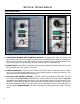
The How To’s For Troubleshooting Suggested Tools List: • • • • • • Ratchet and Sockets: ¼” to ⅝” Screwdrivers: T-20 Torx, Robertson, Straight Blade Penetrating Lubricant (WD-40) High Temperature Silicone (RTV) 500°F Magnehelic Pressure Gauge Needle Nose Pliers, Wire Cutters, Strippers, and Crimpers • • • • • • Open ended Wrenches: ¼” to ½” Cordless Drill / Screwdriver ¼” Insulated connectors Electrical Tape Multimeter Jumper wires Figure 19: Digital Multimeter. Figure 18: Assorted Suggested Tools.
The How To’s For Troubleshooting How To By-Pass The Dial-A-Fire: Female-Female Connector This is for Timer Control models. The dial-a-fire is found behind the right cabinet side. Use a female-female connector to by-pass the diala-fire as shown in Figure 22. Dial-A-Fire Used in Troubleshooting section “The Auger Timer Will Not Function Normally - Timer Control Only“. Figure 22: By-Passing The Dial-A-Fire. How To By-Pass The Start-up Switch: This is models.
The How To’s For Troubleshooting How To By-Pass The Fan Controller: Fan Controller This is for Timer Control models. The fan controller is found on the inside of the right cabinet side. Use a female-female connector to by-pass the fan controller as shown in Figure 24. Female-Female Connector Figure 24: By-Passing The Fan Controller. How To By-Pass The 200°F Manual Reset: The 200°F manual reset is found behind the right cabinet side.
The How To’s For Troubleshooting How To Lubricate The Convection Blower: The convection blower is found behind the right cabinet side. Lubrication Holes The lubrication holes are shown in Figure 26. ONLY use 1 or 2 drops of light oil SAE 20 or 3 in 1, an excess of oil does more harm than good. IMPORTANT: This is only for the EF2, EF3, EF4, Empress FPI, Milan FPI, Meridian FPI, and Meridian FS. Figure 26: Lubrication Holes On The Convection Blower.
The How To’s For Troubleshooting How To By-Pass The 160°F Fan Sensor: The 160°F fan sensor is found behind the left cabinet side. 160oF Fan Sensor Use a male-male connector to by-pass the 160°F fan sensor as shown in Figure 28. Used in Troubleshooting sections “ The 200°F (93°C) High Limit Temperature Sensor Has Tripped“ & “The Auger Light Flashes But The Auger Does Not Turn At All“. Male-Male Connector Figure 28: By-Passing The 160°F Fan Sensor.
The How To’s For Troubleshooting How To By-Pass Exhaust Temperature Sensor/Switch: The exhaust temperature sensor/switch is found behind the left cabinet side. Place both connectors on same side of the exhaust temperature sensor/switch or jumper the wires together as shown in Figure 31. Exhaust Temperature Sensor Place both connectors on same side or jumper the wires together. Used in Troubleshooting section “The Stove Will Not Operate When Hot”.
The How To’s For Troubleshooting How To By-Pass The 120°F Ignitor Temperature Sensor/Switch: The 120°F ignitor temperature sensor/switch is found on the air channel behind the back panel. Use a male-male connector to bypass the 120°F ignitor temperature sensor/switch as shown in Figure 34. 120oF Ignitor Temperature Sensor/Switch Male-Male Connector Caution: Use care when removing the wires, as the sensor can be damaged. NOTE: Convection blower was removed for clarity.
The How To’s For Troubleshooting How To Measure The Exhaust Blower Voltage: The exhaust blower is found behind the left cabinet side. Check the exhaust blower voltage across the blower wires. Set the meter to AC volts and place one probe to each wire of the fan. Normally it is equal to or greater than 114V on #5 setting and equal to or greater than 82V on #1 setting (refer to Figure 37).
The How To’s For Troubleshooting How To Measure The Vacuum Level Produced By The Exhaust Blower: The exhaust blower motor and vacuum switch is found behind the left cabinet side. To measure the exhaust vacuum level, connect the sensor end of the vacuum tube to a magnehelic gauge as shown in Figure 39. Refer to ‘Table 1: Stove Specifications Amperage, Wattages, And For Readings’ in Stove Magnehelic Specifications for the proper readings needed for each model.
Troubleshooting The Stove Will Not Start: Is the stove is plugged in and the wall outlet is supplying power? NO Plug the unit in or fix wall outlet if necessary. YES Is there fuel in the hopper? NO Add pellet fuel to hopper. YES With the stove unplugged, examine all connections. Make sure they are firmly connected and that there are no exposed wires touching the stove (except the chassis ground wire). Check the continuity and placement of connections against the wiring diagrams in this manual.
Troubleshooting Timer Control Only (EF3, 4, 5): Push the start-up switch. Does the stove start? NO Unplug the unit and open the hinged side panels. Are the connections to the fifteen (15) minute start-up timer are correct? YES NO Bypass the start-up switch; refer to The How To’s For Troubleshooting - How To By-Pass The Start-up Switch. Plug the stove back in. Does the stove start? Correct wiring. NO YES Replace the start-up switch. Replace the fifteen (15) minute start-up timer.
Troubleshooting The combustion blower may not be turning fast enough to generate the proper vacuum in the fire box. Visual check, is the blower motor turning? YES Check vacuum levels in the exhaust channel by bypassing the vacuum switch; refer to The How To’s For Troubleshooting - How To By-Pass The Vacuum Switch and How To Measure The Vacuum Level Produced By The Exhaust Blower.
Troubleshooting Timer Control Only (EF2): While HOT, unplug the stove. By pass the auto YES side of the switch with a jumper wire. Plug the stove back in. Does the stove start automatically? Replace the startup switch. The 200°F (93°C) High Limit Temperature Sensor Has Tripped: If this sensor has been tripped find try to determine the reasons for the over heating before pushing red button in. Reset the sensor and determine the cause. Bypass the 160°F (71°C) sensor.
Troubleshooting If the convection blower runs on high at all times (no control with the fan controller), disconnect one wire from the 160°F (71°C) sensor (if equipped it is located on the upper left side of the firewall). Is the motor still running on high? NO YES If control of the convection blower returns to the fan controller or the blower turns off, clean the blades of the fan. Re-connect the sensor and replace the convection fan controller/circuit board.
Troubleshooting The Auger Motor Will Not Function Normally: Check all connections against the unit’s wiring diagram. Are all the connections correct? YES NO Correct the errors. Apply 115V AC directly to the auger motor with a test cord, refer to The How To’s For Troubleshooting - How To Apply Direct Power To The Auger Motor. Does the motor’s armature try to spin even though the auger gear box not turn? YES NO The auger is jammed. Try to break apart jam by poking at the jam through the drop tube.
Troubleshooting Unplug the stove and open the left side access panel; check all connections (especially the auger motor, auger dial-a-fire / circuit board, vacuum sensor, 200°F (93°C) temperature sensor and the timing control module) against the unit’s wiring diagram. Ensure the ignitor has not shorted out. NO Correct any errors. Are all the connections correct? YES NO By pass the vacuum switch, refer to The How To’s For Troubleshooting - How To By-Pass The Vacuum Switch.
Troubleshooting The Auger Timer Will Not Function Normally - Timer Control Only: Is the dial-a-fire turned to the ‘ON’ position’? NO Turn knob clockwise to the ‘ON’ position. You should hear a ‘click’; if you do not the knob may need to be tightened. YES By-pass the auger dial-a-fire control, refer to The How To’s For Troubleshooting - How To By-Pass The Dial-A-Fire. NO Does the auger now cycles very quickly? YES Use a multimeter to check the voltage across the load pins of the timing module.
Troubleshooting NO Check all the electrical connections on the exhaust temperature sensor located on the exhaust channel. Secure the connections. By-pass the ignitor temperature sensor, refer to The How To’s For Troubleshooting - How To By-Pass The 120°F Ignitor Temperature Sensor/Switch. Plug the stove back in. YES Are the connections secure? Does the ignitor work? YES NO Replace the sensor. 140°F (60°C) - EF3 Timer Control 120°F (49°C) - All other models Plug the ignitor in directly.
Troubleshooting NO EF2 Timer Control Only: Is the unit in Auto mode? Switch to Auto. YES Disconnect one (1) of the brown wires from the exhaust temperature sensor. YES OR Disconnect the gray wire from the start-up switch. NO Replace the wiring harness. Does the unit shut down? NO Replace the exhaust temperature sensor. YES Test the start-up switch. To test the switch, the stove must be cold. Pull the plug, then plug the stove back in.
Troubleshooting The Stove Keeps Going Out: The stove goes out and leaves fresh unburned pellets or cigarette-like ashes in the burn pot liner, the fire is going out before the exhaust temperature sensor shuts off. Ensure the slider/ damper is in the correct position. Timer Control Only: Turn the Dial-a-Fire up slightly (poor quality pellets will require slightly higher settings). Circuit Board Only: Set the auger trim till the #1 and #5 lights are illuminated.
Troubleshooting The Auger Light Flashes But The Auger Does Not Turn At All: Has the reset button on the 200°F (93°C) temperature sensor been tripped? YES NO If this sensor has been tripped find the reasons for the over heating before pushing red button in. Check auger for movement. Bypass the 160°F (71°C) sensor.
Troubleshooting Visual check, is the blower motor turning? The combustion blower may not be turning fast enough to generate the proper vacuum in the fire box. YES Check vacuum levels in the exhaust channel by bypassing the vacuum switch; refer to The How To’s For Troubleshooting - How To By-Pass The Vacuum Switch and How To Measure The Vacuum Level Produced By The Exhaust Blower.
Troubleshooting YES Has the exhaust temperature sensor failed? Replace the exhaust temperature sensor. The combustion blower may not be turning fast enough to generate the proper vacuum in the fire box. Visual check, is the blower motor turning? Check vacuum levels in the exhaust channel by bypassing the vacuum switch; refer to The How To’s For Troubleshooting - How To By-Pass The Vacuum Switch and How To Measure The Vacuum Level Produced By The Exhaust Blower.
Flame Characteristics A magnahelic pressure gauge should used when setting the slider/damper the stove. With the slider damper set in the correct location the flame will be brisk, but not too blowing. The flame will also have a yellow to bright orange appearance. There should also be some small embers or sparks exiting the flame and burn pot liner. This is an efficient flame and is the best for proper operation. A small blow torch like flame is a result of too much oxygen being supplied to the fire.
Wiring Diagram EF2 Timer Control: 160oF (71oC) Convection Temperature Switch Purple Purple Black 120oF (49oC) Exhaust Temperature Switch Vacuum Switch Exhaust / Combustion Blower Brown Brown Blue Blue Black Black White Power Cord White Ignitor 120oF (49oC) Ignitor Temperature Switch Auger Motor White Orange 120V White / 220V Light Blue Blue Black White White Brown Grey Purple Auger Timer Convection Blower Input Purple White Green/Yellow White Load Ground Orange Purple Black Black Blue
Wiring Diagram EF3 Timer Control: 160oF (71oC) Convection Temperature Sensor Purple Purple 140oF (60oC) Exhaust Temperature Sensor Vacuum Switch Exhaust/Combustion Blower Brown Brown Blue Blue Brown Brown Purple Black Power Cord Brown Brown Ignitor 120oF (49oC) Ignitor Temperature Sensor Orange Blue Orange Grey Auger Motor Auger Timer Convection Blower Brown White Black Black 120 V Black 220 V Brown Purple Purple Purple Yellow Yellow Dial-A-Fire Black Grey Blue Grey Purple Start-Up Timer B
Wiring Diagram EF2, EF3, & EF4 Timer Control With Thermostat Interface: 160oF (71oC) Convection Temperature Sensor 160oF (60oC) Exhaust Temperature Sensor Grey Grey Red Orange Yellow Yellow Dial-A-Fire Brown Brown Vacuum Switch Brown Brown Purple Black Phase Controller Thermostat Interphase Input Orange White White Black Black Auger Motor Red Red Auger Timing Module Purple Purple Purple Red Input Load Start-Up Timer Brown Purple Blue Grey Black Grey Input Load Black Black Brown Brown W
Wiring Diagram EF4: 160oF (71oC) Convection Temperature Sensor Purple Purple 140oF (60oC) Exhaust Temperature Sensor Vacuum Switch Exhaust/Combustion Blower Brown Brown Blue Blue Brown Purple Black Ground Power Cord Ignitor 120oF (49oC) Ignitor Temperature Sensor Auger Motor Grey Grey Phase Control Convection Blower Brown Brown Orange Blue Orange Grey Brown White Black Black Grey Grey Brown Auger Timer Dial-A-Fire Purple Black Brown Purple Grey Blue Grey Purple Start-Up Timer Black
Wiring Diagram EF5 (Evolution) - Timer Control: Red Orange Orange Yellow Dial-A-Fire Blue Blue Vacuum Switch Exhaust/ Combustion Blower Brown Black 120oF (49oC) Exhaust Temperature Sensor Brown Brown Grey Grey Thermostat Interphase Exhaust Trim Power Cord Auger Trim White Black o o Black 120 F (49 C) Ignitor Temperature Black Brown Brown To 12 Volt Thermostat Brown White Black Black Orange Grey Grey Auger Motor Convection Blower Orange Grey Jumper Wire with Resistor Blue Combustion Phase C
Wiring Diagram EF5 (Evolution) & Mini - DHC 2000: White Black Armor Cable Supplied Grey Vacuum Switch Grey Black White Blue White Combustion Blower Optional Exterior Exhaust Blower Brown o Power Cord o 120 F (49 C) Exhaust Temperature Sensor Ground Brown Black Red Black White 115V White 220V Blue Common J2 115V Black 220V Brown Hot 5 Amp Fueses Ignitor Thermostat 5V DC Black Convection Blower Purple White Auger Motor 200oF (93oC) High Limit Temperature Sensor Yellow White Orange Ora
Wiring Diagram Meridian Circuit Board - DHC 2000: Grey Vacuum Switch Grey Blue Combustion Blower White Brown Power Cord 120oF (49oC) Exhaust Temperature Sensor Brown Black Black Red White Ignitor Black 200oF (93oC) High Limit Temperature Sensor 62 White Black Common Hot 5 Amp Fuses Thermostat 5 V DC Black White Purple White Auger Motor J2 Black 160oF (71oC) Convection Blower Sensor Convection Blower Ground Yellow White Orange Orange Orange Orange Purple Blue Yellow Red Grey Grey
Wiring Diagram Empress FS - DHC 2000: White Black Armor Cable Supplied Grey Vacuum Switch Grey Black White Blue White Combustion Blower Optional Exterior Exhaust Blower Brown o Power Cord o 120 F (49 C) Exhaust Temperature Sensor Ground Brown Black Red Black White 115V White 220V Blue Common J2 115V Black 220V Brown Hot 5 Amp Fueses Ignitor Thermostat 5V DC Black Convection Blower White Orange Orange Purple Blue Yellow Purple White Auger Motor 200oF (93oC) High Limit Temperature Sen
Wiring Diagram EF5 (Evolution), Mini, & Empress FS - DHC 3000, 4000, & 4100: Armor Cable Supplied Optional Exterior Exhaust Blower Grey Grey Black Combustion Blower Vacuum Switch White White Blue Brown Exhaust Temperature Sensor Power Cord Brown Ground Thermostat 5 Amp Fuse Black White Orange Orange Purple Blue Yellow Red Grey Grey Brown Brown Red Red 64 115V White 220V Blue 115V Black 220V Brown Connect Thermostat Here Hot Red White Black Black Common Ignitor Purple White Yellow Whit
Wiring Diagram Meridian - DHC 3000, 4000, & 4100: Armor Cable Supplied Optional Exterior Exhaust Blower Grey Grey Black Combustion Blower Vacuum Switch White White Blue Brown Exhaust Temperature Sensor Power Cord Brown Ground Thermostat 5 Amp Fuse Black White Orange Orange Purple Blue Yellow Red Grey Grey Brown Brown Red Red 115V White 220V Blue 115V Black 220V Brown Connect Thermostat Here Hot Red White Black Black Common Ignitor Convection Temperature Sensor Purple White Yellow Whit
Wiring Diagram Empress FPI & Milan: Orange Orange Vacuum Switch Blue Combustion Blower Daughter Board Red Connect Thermostat Here White Red Brown 120oF (49oC) Exhaust Temperature Sensor Ground Power Cord Brown Black Black Red White 115V White 220V Blue Common Thermostat Selector Pins 115V Black 220V Brown Hot Mother Board Ignitor Convection Blower Purple White Auger Motor 200oF (93oC) High Limit Temperature Sensor 66 Yellow White Grey Grey Black White Grey Grey Purple Blue Yellow Red Oran
Wiring Diagram Windsor: White Black Armor Cable Supplied Grey 200oF (93oC) High Limit Temperature Sensor Grey Black White Blue White Combustion Blower Optional Exterior Exhaust Blower Brown o Power Cord o 120 F (49 C) Exhaust Temperature Sensor Ground Brown Black Red Black White 115V White 220V Lt Blue Common Ignitor Hot 5 Amp Fueses Black Purple White Auger Motor Vacuum Switch Thermostat 5V DC Black 160oF (49oC) Convection Temperature Sensor Convection Blower J2 115V Black 220V B
Wiring Diagram Maxx: Brown Exhaust Temperature Sensor Brown Combustion Blower White Blue 120V Grounded Plug Red White Black Black Ignitor Ground Thermostat White Black 5 Amp Fuse Red Black Yellow White Blue Brown Brown Purple Grey Orange Orange Red Red 68 Connect Thermostat Here White Auger Motor Yellow Yellow White Purple High Limit Temperature Sensor Vacuum Switch Convection Blower
Wiring Diagram M55-FS - DHC 4110: Red Combustion Blower Black Black Blue 2µF Capacitor Brown Brown Blue Blue Black White Red White Green Ground 120V Ground Plug Red White Thermostat Exhaust Temperature Sensor Air Pump Ignitor Ground Green White Black 5 Amp White Blue/Yellow Black White Yellow Red Yellow Purple Blue Brown Brown White Purple White Grey Grey Grey Grey Orange Orange Orange Orange Agitator Motor Auger Motor Convection Blower Vacuum Switch High Limit Temperature Swi
Wiring Diagram Omega: Brown Brown White Combustion Blower Blue 120V Grounded Plug Thermostat N Green White Black L 5 Amp Fuse Red White Air Pump Red White Ignitor Ground White Blue/Yellow Red Black Yellow White Blue Brown Brown Purple Grey Grey Orange Orange Red Red 70 Connect Thermostat Here Exhaust Temperature Sensor White Yellow White Purple Agitator Motor Auger Motor Convection Blower Vacuum Switch High Limit Temperature Sensor
Components Of A Pellet Stove 120°F (49°C) N/C Ignitor Temperature Sensor: This sensor (mounted on the exhaust channel) will turn the ignitor OFF when the exhaust temperature reaches 120°F (49°C). This is a normally closed sensor that open when it is heated to 120°F (49°C). 160°F (71°C) Convection Fan Sensor: When this sensor mounted on the left side firewall reaches 160°F (71°C) the convection blower will go to high cooling the unit before it overheats.
Components Of A Pellet Stove Exhaust Temperature Sensor: This sensor is anormally open, is mounted on the exhaust blower housing, and has two functions: 1. Should the fire go out, this sensor will shut the stove off when the exhaust temperature drops below its set point. 2. When the auger is turned OFF via the dial-a-fire, the exhaust temperature will drop, when the exhaust temperature drops below set point the sensor will shut the stove OFF.
Glossary Burn Pot And Burn Pot Liner: This is were the pellets are dropped from the hopper and then burned. Blower Mechanism: Device used either to remove exhaust gases from the stove or move air over the heat exchanger and into the room Clearance To Combustibles: The distance required to maintain a safe operating distance to a combustible material. Clinkers: Creosote builds up from a higher water content pellet or insufficient fresh air supply.
Warranty Sherwood Industries Ltd. is the manufacturer of the Enviro line of heating products. At Sherwood Industries, our commitment to the highest level of quality and customer service is the most important thing we do. Each Enviro stove is built on a tradition of using only the finest materials and is backed by our Exclusive Lifetime Limited Warranty to the original purchaser. With Enviro, you’re not just buying a stove, you’re buying a company with years of unequalled performance and quality.
Warranty Exclusions and Limitations: 1. This Warranty does not cover tarnish, discoloration or wear on the plating or paint. 2. This Warranty excludes wear and tear or breakage caused by cleaning, moving or service on log set. 3. A qualified installer must install this stove or fireplace. This Limited Warranty covers defects in materials and workmanship only if the product has been installed in accordance with local building and fire codes; in their absence, refer to the owner’s manual.
Warranty 17. Damage to plated surfaces caused by fingerprints, scratches, melted items, or other external scores and residues left on the plated surfaces from the use of abrasive cleaners or polishes is not covered in this warranty. 18. The Limited Warranty does not cover tarnish, discoloration or wear on the plated surfaces. 19. The paint on the Metal Brick Liner may peel. This is due to the extreme conditions applied to the paint during normal usage. It is not a flaw and is not covered under warranty. 20.
SHERWOOD INDUSTRIES LTD. 6782 OLDFIELD RD.