SHERWOOD INDUSTRIES IS AN ENVIRONMENTALLY RESPONSIBLE COMPANY. THIS MANUAL IS PRINTED ON RECYCLED PAPER. PLEASE KEEP THESE INSTRUCTIONS FOR FUTURE REFERENCE PELLET STOVE MERIDIAN OWNER’S MANUAL PLEASE READ THIS ENTIRE MANUAL BEFORE INSTALLATION AND USE OF THIS PELLET BURNING ROOM HEATER. FAILURE TO FOLLOW THESE INSTRUCTIONS COULD RESULT IN PROPERTY DAMAGE, BODILY INJURY OR EVEN DEATH Contact your building or fire officials about restrictions and installation inspection requirements in your area.
Table of Contents Introduction..............................................................................................................3 Pellet Quality..................................................................................................3 Rating Label Location......................................................................................4 Important Safety Data....................................................................................4 Safety Warnings And Recommendations.....
Introduction PELLET QUALITY: PELLET QUALITY IS IMPORTANT, PLEASE READ YOUR ENVIRO PELLET STOVE HAS BEEN DESIGNED TO BURN WOOD PELLETS ONLY. DO NOT USE ANY OTHER TYPE OF FUEL, AS THIS WILL VOID ANY WARRANTIES STATED IN THIS MANUAL. CAUTION: It is important to select and use only pellets that are dry and free of dirt or any impurities such as high salt content. Dirty fuel will adversely affect the operation and performance of the unit and will void the warranty. The Pellet Fuel Industries (P.F.I.
Introduction RATING LABEL LOCATION: Freestanding: The rating label is located on the inside of the hopper lid. Insert: The rating label is located on the hopper cover. IMPORTANT SAFETY DATA: TO PREVENT THE POSSIBILITY OF A FIRE, THIS APPLIANCE MUST BE PROPERLY INSTALLED BY FOLLOWING THE INSTALLATION INSTRUCTIONS. PLEASE READ THIS ENTIRE OWNER’S MANUAL BEFORE INSTALLING OR OPERATING YOUR ENVIRO PELLET STOVE. FAILURE TO FOLLOW THESE INSTRUCTIONS MAY RESULT IN PROPERTY DAMAGE, BODILY INJURY OR EVEN DEATH.
Introduction Glass: Do not abuse the glass by striking or slamming the door. Do not attempt to operate the stove with broken glass. The stove uses ceramic glass. Replacement glass must be purchased from an ENVIRO dealer. Do not attempt to open the door and clean the glass while the unit is in operation or if glass is hot. Flammable Liquids: Never use gasoline, gasoline-type lantern fuel, kerosene, charcoal lighter fluid, or similar liquids to start or “freshen up” a fire in the heater.
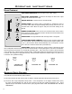
Operating Instructions STOVE CONTROLS: HEAT LEVEL INDICATOR: Shows the Heat Level output setting. HEAT LEVEL ADJUSTMENT: This button will change the Heat Level output setting of the stove from low to high ON/OFF BUTTON: Is used to turn the unit ON and OFF SYSTEM LIGHT: The System Light is responsible for signaling the state of the control board. When the light is flashing during start-up, the stove is in an automatic start mode.
Operating Instructions C) This unit has a convection fan control over-ride. This function causes the convection fan to reach its full speed when the temperature at the back of the firebox reaches 160° F (71° C). This is a normal safety feature of your unit. D) The unit is equipped with a vacuum switch to monitor the venting; if it becomes blocked the vacuum switch will turn off the auger and the #2 light on the control board will flash.
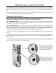
Operating Instructions SLIDER/DAMPER SETTING: THE SLIDER / DAMPER MUST BE SET AT TIME OF INSTALLATION. A Qualified Service Technician or Installer must set the Slider Damper. The slider damper should be set only on a hot stove (operating for 30 minutes or more) by placing a Magnahelic Pressure Gauge in the firebox (test port is located in the center of the stove just below the door opening). Set the slider damper so that the pressure reads 0.11” w.c. (.
Operating Instructions OPERATING YOUR PELLET STOVE: PRE-BURN INSTRUCTIONS: The burn pot liner holes must be clear and the liner installed properly against the ignitor tube for proper operation. Check the hopper for enough pellets to start the unit. DO NOT OPERATE THE UNIT WITH THE DOOR OR ASH PAN AJAR MANUAL MODE: To START: Press the ON / OFF Button. The stove will turn on. The System Light will flash.
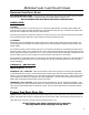
Routine Cleaning and Maintenance The following list of components should be inspected and maintained routinely to ensure that the appliance is operating at its optimum and giving you excellent heat value: 2-3 DAYS/WEEKLY Burn Pot and Liner Ash Pan Inside Firebox Door Glass Heat exchanger tubes Ash pan and Door gaskets Door Latch SEASON or 2 TONS OF FUEL Exhaust Vent Fresh air Intake Tube Blower Mechanisms Heat exchanger tubes Behind firebox liners All Hinges Post Season Clean-up TOOLS REQUIRED TO CLEAN UN
Routine Cleaning and Maintenance ���� ������� ��� HEAT EXCHANGER TUBES (weekly) Open the door and the rod is located under the unit top, in the center of the stove just behind the door (see figure to left). This handle is to be pushed in and out a few times (ONLY WHEN THE UNIT IS COLD) in order to clean away any fly ash that may have collected on the heat exchanger tubes.
Installation DECIDING WHERE TO LOCATE YOUR PELLET APPLIANCE: 1. Check clearances to combustibles. 2. Do not obtain combustion air from an attic, garage, or any unventilated space. Combustion air may be obtained from a ventilated crawlspace. 3. Do not install the stove in a bedroom. 4. You can vent the stove through an exterior wall behind the unit or connect it to an existing masonry or metal chimney (must be lined if the chimney is over 6” (15.2cm) in diameter, or over 28 sq. inches (180.
Installation FLOOR PROTECTION: Your MERIDIAN pellet stove requires floor protection. The floor protection must be non-combustible, extending beneath the stove the full width and depth of the unit including 6 “ (15cm) in front for ember protection. FREESTANDING DIMENSIONS: WIDTH: HEIGHT: DEPTH: 24 7⁄8 inches 32 1⁄2 inches 24 3⁄4 inches (63.2 cm) (82.6 cm) (63.
Installation INSERT DIMENSIONS: WIDTH: HEIGHT: DEPTH: DEPTH FROM FRONT OF UNIT TO SURROUND: 23 22 23 12 3⁄4 7⁄8 7⁄8 7⁄8 inches inches inches inches (60.4 (64.6 (60.5 (32.6 cm) cm) cm) cm) FREESTANDING CLEARANCES TO COMBUSTIBLES AND MINIMUM ALCOVE SIZE: ��� �� �� ��� �� ��� Maintain these clearances to combustibles. SIDE WALL TO UNIT 6 inches (20.4 cm) BACK WALL TO UNIT 3 inches ( 7.6 cm) ADJACENT WALL 2 inches ( 5.0 cm) This unit may be installed MIN. ALCOVE WIDTH MIN. ALCOVE HEIGHT MIN.
Installation VENT TERMINATION REQUIREMENTS: 1. Do not terminate the vent in any enclosed or semi-enclosed areas such as a carport, garage, attic, crawlspace, narrow walkway, closely fenced area, under a sundeck or porch, or any location that can build up a concentration of fumes such as stairwells, covered breezeway, etc. 2. Vent surfaces can become hot enough to cause burns if touched by children. Non-combustible shielding or guards may be required. 3. Termination must exhaust above the inlet elevation.
Installation OUTSIDE FRESH AIR CONNECTION: ����� ��� ����� ��� �������� ����� ��� Outside fresh air is mandatory when installing this unit in airtight homes and mobile homes. When connecting to an outside fresh air source, do not use plastic, combustible pipe. Only 2” ID (inside diameter) steel, aluminum or copper pipe should be used. It is recommended, when you are installing a fresh air system, to keep the number of bends in the pipe to a minimum.
Installation THROUGH WALL INSTALLATION: The MERIDIAN can be vented through the wall using two different methods. Only use vent of (L or PL) type with an inside diameter of 3 or 4 inches (7.6 or 10.1 cm) VENT INSTALLATION: INSTALL VENT AT CLEARANCES SPECIFIED BY THE VENT MANUFACTURER. A chimney connector shall not pass through an attic or roof space, closet or similar concealed spaces, or a floor, or ceiling.
Installation STRAIGHT THROUGH WALL INSTALLATIONS: The termination must be 12 inches (30 cm) from the outside wall and 12 inches (30 cm) above the ground. Wall framing Horizontal frame for thimble Vent pipe A 45° elbow with a rodent screen may be used in place of the termination cap (or stainless steel termination hood).
Installation VERTICAL INSTALLATION: 1. Choose a stove location that is ideal. See the section Deciding Where to Locate Your Pellet Appliance. 2. Place the unit on the hearth pad (if installed on a carpeted surface) and space the unit in a manner so when the pellet vent is installed vertically, it will be 3” (7.6 cm) away from a combustible wall. 3. Locate the center of the fresh air intake pipe on the unit. Match that center with the same point on the wall and cut a hole about 2 1⁄8” (5.4 cm) in diameter.
Installation HEARTH MOUNT INSTALLATION: 1. Lock fireplace damper in the open position. 2. Install positive flue connector at the fireplace dampers. 3. Connect a Tee or a 90° degree elbow to the exhaust pipe. 4. Install flexible stainless steel liner or listed pellet vent to the top of the chimney.
Installation EXTERIOR MOUNTED EXHAUST BLOWER: The MERIDIAN can be equipped with an externally mounted exhaust blower (PART #20-070). This optional kit will include all components necessary to install the exhaust blower on any external vertical wall surface. Choose a location for your stove that meets the requirements stated in this manual and allows installation with the least amount of interference to house framing, plumbing, wiring, etc. INCLUDED IN THE EXTERIOR MOUNTED EXHAUST BLOWER KIT ARE: 1.
Installation EXTERIOR MOUNTED EXHAUST BLOWER: NOTE: Ensure that all vent connections are installed by placing three screws evenly spaced and a small bead of high temperature silicone at each chimney connection. Also ensure that all vertical vent sections are properly supported and that all clearances to combustibles are maintained in accordance with the vent manufacturer’s specifications.
Installation THROUGH WALL VERTICAL INSTALLATION: Follow the previous pages for through wall installations. Ensure that vent pipe is properly secured to wall using wall straps. Maintain clearances to combustibles on vent pipe as well as unit.
Installation MASONRY FIREPLACE INSERT INSTALLATION: The Fireplace insert model requires a surround faceplate and a pedestal. When installing this unit, ensure that the pedestal is removed from the inside of the hopper and installed on the bottom of the unit (see “Installation of Fireplace Insert Pedestal and Leveling Legs” and “Assembly and Installation of Insert Surround Panels”.
Installation INSTALLATION OF FIREPLACE INSERT PEDESTAL AND LEVELING LEGS: There are two parts to the Meridian insert pedestal and they can be found inside the hopper. Place unit on its’ back. Two hex head screws are used on each side of the pedestal (refer to figure on right). Using a 5/16” wrench or socket attach the pedestal to the bottom of the unit. OPTIONAL: There are two leveling legs and they can be found inside the manual bag.
Installation INSTALLATION AND REMOVAL OF CONTROL PANEL IN THE SURROUND PANEL: When installing the circuit board control panel into the surround panel, the surround does not need to be assembled The circuit board will be found in the firebox. Place the circuit board control panel on the backside of the right surround panel so the hinge is on the outside and the top and bottom holes on the control panel line up with those on the surround.
Installation PLATED TRIM INSTALLATION: TO AVOID PERSONAL INJURY DO NOT REMOVE OR REPLACE TRIMS WHEN PELLET STOVE IS HOT! KIT COMPONENTS: Quantity Description 2 Upper Cabinet Trim 2 Lower Cabinet Trim 1 Top Trim 3 Louver 4 #8 nut plated (spares) TOOLS REQUIRED: ●T20 screwdriver ●11/32” socket REMOVAL OF SIDE TRIMS: Right cab side with upper and lower cabinet trims. When stove is off and cool, open the door.
Installation REMOVAL OF LOUVER BAR SET: Door must be open. The three arrows in figure 3 point to three of the nuts that hold the louvers on. There are three nuts on each end. Remove the six nuts by hand; if the nuts are tight, a 11/32” socket can be used. When removing the louvers, pull one end of the louver up over the stud. If it is difficult to remove the louver, push on one side from the front, then pull the other end off the second stud.
Troubleshooting DO NOT: ● Service the stove with wet hands. The stove is an electrical appliance, which may pose a shock hazard if handled improperly. Only qualified technicians should deal with possible internal electrical failures. ● Do not remove from the firebox any screws without penetrating oil lubrication. WHAT TO DO IF: The stove will not start. The stove will not operate when hot. The exhaust blower will not function normally. The convection blower will not function normally.
Troubleshooting üCheck the Exhaust Blower voltage across the blower wires (>=114V on #5 setting and >= 82V on #1 setting). – Replace the Circuit Board if the Voltage reading is less than 82V. with a line voltage >115Vac. üCheck Vacuum levels in the exhaust channel by bypassing the Vacuum Switch, then remove the Vacuum hose from Vacuum Switch. Check exhaust vacuum readings by placing the open end of the Vacuum Hose on a Magnahelic Gauge (readings must be above .10” W.C. on low fire).
Troubleshooting Auger light flashes but auger motor does not turn at all: üIf the Auger gear box does not turn but the motor’s armature does try to spin then the auger is jammed. – Try to break apart jam by poking at the jam through the drop tube. If this fails then empty the hopper and remove the Auger Cover **Remember to re-seal the cover after installation** The 200°F ( 93°C) high limit temperature sensor has tripped.
Wiring Diagram 32
Parts List Part Description Number Part Description Number 20-040 Control Panel Door EF-178 Freestanding Ash Pan Latch 50-178 Circuit Board 115V 50-523 Freestanding Hopper Lid Handle 50-179 Circuit Board Decal - 115V 50-620 Freestanding Body Trim Kit - Pewter 50-323 Control Panel Touch Latch 50-621 Freestanding Body Trim Kit - Gold 50-330 Circuit Board Control Panel 50-622 Freestanding Body Trim Kit - Antique Copper 50-473 Combustion/ Exhaust Blower - 115V 50-659 Freestanding Ash Pa
Parts Diagram - Freestanding Steel Top trim Painted 50-671 Gold 50-672 Pewter 50-673 Antique copper 50-674 Hopper lid handle 50-523 Freestanding back grill 50-675 Freestanding upper cabinet trim (1 piece) Painted 50-666 Gold 50-667 Pewter 50-668 Antique copper 50-669 Freestanding lower cabinet trim (1 piece) Painted 50-662 Gold 50-663 Pewter 50-664 Antique copper 50-665 Freestanding cabinet side left 50-661 Freestanding hopper lid 50-676 Freestanding pedestal 50-660 Freestanding top front 50-677 C
Insert oversized panel set 50-770 Insert oversized panel - Left 50-820 Insert oversized panel - Right 50-821 Insert oversized panel - Top 50-822 Insert regular panel set 50-769 Insert regular panel - Left 50-817 Insert regular panel - Right 50-818 Insert regular panel - Top 50-819 Hopper cover 50-828 Insert cabinet side left 50-823 Insert top front 50-825 Insert hopper lid 50-827 Insert ash pan 50-826 Insert cabinet side right 50-824 Top trim Painted 50-671 Gold 50-672 Pewter 50-673 Antique copper 50
Parts Diagram - Components 200°F (93°C) manual reset high limit sensor EF-016 Convection blower - 115V EF-002 Circuit board - 115V 50-178 Auger EF-025 Brass auger bushing EF-065 Auger motor - 115V EF-001 MERIDIAN COMPONENTS ������� ���� 160°F (71°C) Fan temperature sensor EF-013 Slider/damper rod EF-064 120°F (49°C) exhaust temperature sensor EC-001 Combustion/exhausr blower - 115V 50-473 Vacuum switch - 115V EF-017 36
Warranty Sherwood Industries Ltd. gives a five year limited warranty on all steel manufactured parts. A one-year warranty is provided on all electrical components. The above limited warranties are extended only to the original purchaser. There is no warranty on the following parts: ● Fiberglass rope baskets ● refractory material ● burn pot liner ● paint ● enamel finish or gold plating where it applies ● vacuum hose. **NOTE: The paint on the brick firebox lining may peel.
Installation Data Sheet The following information must be recorded by the installer for warranty purposes and future reference.