
Installation Guide


GENERAL: Todas las conexiones eléctricas deben estar de acuerdo con las
normas locales y el Código Eléctrico Nacional (NEC). Asegúrese de leer
estas instrucciones y estudie los diagramas antes de comenzar. Si usted no
está familiarizado con las conexiones del cableado eléctrico apropiado,
obtenga los servicios de un electricista calificado.
ANTES DE COMENZAR
Compruebe si la fuente de energía es adecuado para la carga eléctrica
adicional. El poder debe ser suministrada por 110/120 voltios, 60 Hz circuito
único. Un estándar de 120 voltios, ramal Amperios 15 está diseñado para
llevar una carga máxima de 1800 vatios. Recomendamos que la potencia
total de todas las luces y aparatos en ese circuito no supere el 80% o 1440
vatios de la capacidad eléctrica máxima.
1. Este producto está diseñado para ser usado con cables de NM
(Romex). Las ranuras de alivio de tensión son proporcionadas para
acomodar cables NM. No utilice cables BX (blindado) ya que no
encajarán en las ranuras del alivio de tensión.
2. Este accesorio es un accesorio tipo IC. Puede entrar en contacto
directo y ser completamente cubierto con aislamiento térmico que
tiene un valor-R de 3,85 o menos. Algunos tipos de aislamiento
que cumplan con este requisito son manta bateo/rodillo y relleno
suelto soplado. No lo instale en un techo con aislante tipo espuma
en espray. Cualquier parte de la lámpara puede venir en contacto
directo con cualquier material combustible, como un tablero del techo
viga o suelo.
3. Este luminario requiere una superficie de techo existentes, tales como
paneles de yeso, para la instalación. Para instalar este accesorio, un
agujero debe ser hecho en la superficie del techo en la ubicación
deseada. Después, el cableado de alimentación (cable NM) necesita
ser instalado desde la fuente de poder hasta el agujero.
4. Esta luminaria está diseñada para superficies de techo que son de
3/4“ de espesor o menos. No utilice este aparato en superficies de
techo que son más gruesas de 3/4".
5. Para prevenir daños a cables o abrasión, no exponga el cableado a los
bordes de la hoja de metal u otros objetos puntiagudos.
DESEMBALE EL APARATO
Compruebe el contenido de la caja. Usted debe tener:
• 1 – Easy–UP™ Borde con Anillo Decorativo Magnético
• 1 – Plantilla para Agujero (4 ¼” de diámetro)
INSTALAR EL LUMINARIO
NOTA: Primero apague la electricidad en el interruptor de circuito o la caja
de fusibles. Apagando la electricidad por medio del uso de un interruptor de
pared no es suficiente para evitar descargas eléctricas.
1. Seleccione la ubicación de la luminaria, teniendo en cuenta el requisito
de despeje de 5” de profundidad, la ubicación de las viguetas del techo
y la accesibilidad para el suministro eléctrico. Marque la ubicación
seleccionada con un círculo usando la plantilla provista.
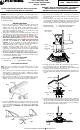
2. Con una sierra de calar crea un agujero 4¼” de la superficie del techo.
(Fig. 1) (Nota: Asegúrese de no hacer el agujero más grande que
especificado por la plantilla. Un agujero de gran tamaño puede evitar la
instalación correcta.)
WARNING - RISK OF ELECTRIC SHOCK. DISCONNECT
MAIN POWER AT FUSE OR CIRCUIT BREAKER
BEFORE INSTALLING OR SERVICING THE FIXTURE.
LED 4” INSTALACIÓN EMPOTRADA TRIM
INSTRUCCIONES - Easy-UP ™ K1F4WHWH2C MODELO
CON ANILLO MAGNETICO DECORATIVO
QUESTIONS? CALL TOLL
FREE 1-866-992-2278
Por favor, lea cuidadosamente y guarde estas
instrucciones, ya que puede necesitar en una fecha
posterior.
Fig. 1
Viguetas del techo
Techo
3. Run non-metallic (NM) cable (also known as Romex) from your circuit
breaker or fuse panel to the hole, providing 6” (15,2 cm) to 8” (20,3
cm) of slack extending below the hole. Cable having up to 12 AWG
wiring may be used. (Fig. 2) (WARNING - Use cables having wires
rated 90°C or more.)
Techo
Cable
Agujero
Fig. 2
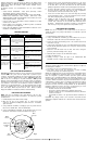
4. Open the top door of the junction box. Insert about 5 or 6 inches of
the NM cable into the junction box through one of the provided strain-
relief slots. (Fig. 3)
5. Remove at least 3” of the cable’s outer sheath and remove the plastic
or paper over-wrap. Strip approximately 3/8” of insulation from the
ends of all supply wires. Using the wire connectors (not provided),
make the following wire connections within the junction box (Fig. 3):
WHITE Fixture Wire to WHITE (NEUTRAL) Supply Wire
BLACK Fixture Wire to BLACK (HOT) Supply Wire
Strain-relief
slot
NM cable
Top door
Wire connector
Junction
Box
6. Carefully stuff the wires and the wire connections into the junction box.
Close the junction box top door. Tighten the fastening screw.
7. Raise the EasyUp™ trim up to the ceiling hole, while simultaneously
pushing the excess NM cable into the hole. (Fig. 4)
8. Flip up and squeeze the spring-loaded wings against the junction box,
as shown, and insert the EasyUp™ trim into the hole, junction box
first. (Fig. 4)
Spring-loaded
wing
Junction
Box
9. Continue inserting the EasyUp™ trim into the hole, while continuing
to squeeze the spring-loaded wings. When the wings reach the hole
edge, release them and push up the EasyUp™ trim until both wings
flip down onto the ceiling surface. (Fig. 5) The decorative ring of the
EasyUp™ trim should be flush against the ceiling surface.
Spring-loaded
wing
Ceiling
ALL RIGHTS RESERVED. COPYRIGHT LITECHOICE 2014
Hole
Cable NM
Fig. 3
Fig. 4
Fig. 5