
Installation Guide

WARNING - RISK OF ELECTRIC SHOCK. DISCONNECT
MAIN POWER AT FUSE OR CIRCUIT BREAKER
BEFORE INSTALLING OR SERVICING THE FIXTURE.
LED 4” RECESSED DOWNLIGHT INSTALLATION
INSTRUCTIONS – MODEL EV407943
Please read carefully and save these instructions,
as you may need them at a later date.
GENERAL: All electrical connections must be in accordance with local and
National Electrical Code (N.E.C.) standards. Be sure to read these
instructions and review the diagrams thoroughly before beginning. If you are
unfamiliar with proper electrical wiring connections obtain the services of a
qualified electrician.
BEFORE YOU BEGIN
1. Check if the power source is suitable for the added electrical load.
Power should be supplied by a 110/120 volt, 60 Hz single circuit. The
rated wattage is marked on this product. When installing multiple lights
on a branch circuit, follow NEC guidelines to determine the maximum
number of allowable lights (1400 Watts for a 120 Volt, 15 Ampere
circuit). If a dimmer is used, do not exceed its rated wattage limit.
2. This fixture is an IC type fixture. It may come in direct contact and
be completely covered with thermal insulation that has an R-value
of 3.85 or less. Some insulation types that meet this requirement
are blanket batting/roll and blown-in loose fill. Do not install in a
ceiling with spray foam type insulation. Any part of the fixture may
come in direct contact with any combustible material, such as a ceiling
joist or floor board.
3. This fixture requires an existing ceiling surface, such as drywall, for
installation. To install this fixture, a hole needs to be made into the
ceiling surface at the desired location. Then, power supply wiring (NM
cable) needs to be installed from the power source to the hole.
4. This fixture is designed for ceiling surfaces that are 3/4” thick or less.
Do not use this fixture on ceiling surfaces that are thicker than ¾”.
5. This fixture may be installed over a wet or damp location such as a
shower stall or bathtub enclosure. The area above the ceiling surface
must, however, be a dry location.
6. To prevent wiring damage or abrasion, do not expose wiring to edges
of sheet metal or other sharp objects.
UNPACK THE FIXTURE
Check the contents of the box. You should have:
• 1 – Fixture
• 1 – Hole Template (4 ¼ ” diameter)
• 3 – Wire Connectors
INSTALLING THE FIXTURE
NOTE: First turn off electricity at the circuit breaker or the fuse box. Turning
the power off by using a wall switch is not sufficient to prevent electrical
shock.
1. Choose the location for the fixture, taking into consideration the 5”
depth clearance requirement, the location of ceiling joists and the
accessibility for the electrical supply. Mark the selected location with a
circle using the provided template.
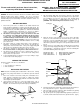
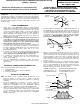
2. Using a keyhole saw make a 4 ¼ ” hole in the ceiling surface. (Fig. 1)
(Note: Be sure not to make the hole any larger than specified by the
template. An oversized hole may not allow for proper installation.)
Fig. 1
Ceiling joist
Ceiling
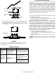
3. Run non-metallic (NM) cable (also known as Romex) or an armored
cable (also known as BX) from your circuit breaker or fuse panel to the
hole, providing 6” (15,2 cm) to 8” (20,3 cm) of slack extending below
the hole. Cable having up to 12 AWG wiring may be used. (Fig. 2)
(WARNING - Use cables having wires rated 90°C or more.)
Ceiling
Cable
Hole
Fig. 2
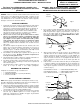
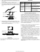
4. Open the side door of the junction box. If you are using a BX cable,
remove one of the round knockouts located on the top or sides of the
junction box. If you are using NM cable, remove a rectangular knockout
on the back of the junction box. Insert about 5 or 6 inches of the NM
cable into the junction box through one of the provided strain-relief slots.
(Fig. 3)
5. Remove at least 3” of the cable’s outer sheath and remove the plastic
or paper over-wrap. Strip approximately 3/8” of insulation from the ends
of all supply wires. Using the wire connectors, make the following wire
connections within the junction box (Fig. 3):
WHITE Fixture Wire to WHITE (NEUTRAL) Supply Wire
BLACK Fixture Wire to BLACK (HOT) Supply Wire
Fixture GROUND Wire to Supply GROUND Wire
Strain-relief
slot
Side door
Wire
connector
Junction
Box
Fig. 3
ALL RIGHTS RESERVED 2016
6. Carefully stuff the wires and the wire connections into the junction box.
Close the junction box top door. Tighten the fastening screw.
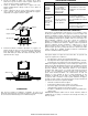
7. Raise the fixture up to the ceiling hole, while simultaneously pushing
the excess NM cable into the hole. (Fig. 4)
8. Flip up and squeeze the spring-loaded wings against the junction box,
as shown, and insert the fixture into the hole, junction box first. (Fig. 4)
QUESTIONS? CALL THE
TOLL-FREE NUMBER
LOCATED ON THE PACKAGE