
Instructions / Assembly

INSTALLATION & OPERATION INSTRUCTIONS
4” NEW CONTRUCTION NON-IC RECESSED HOUSING WITH SLIDE-N-LOCK ™ FEATURE
CAUTION
Before assembling your lighting fixture, refer to the section titled
ELECTRICAL CONNECTIONS. If you feel you do not have electrical wiring
experience, refer to a do-it-yourself wiring handbook or have your fixture
installed by a qualified licensed electrician.
ALL RIGHTS RESERVED. COPYRIGHT ENVIROLITE 2019
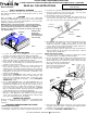
NOTE:This fixture is a Non-IC type fixture. For Non-IC type fixtures,
any insulation must be spaced at least 3” from the housing (including
the can and junction box) and at least 1/2” from any combustible
material (e.g. ceiling joists, floor boards), except for points of support
(e.g. drywall). (FIG. 1)
Insulation must
be spaced a
minimum distance
of 3” from any part
of the housing.
FIG. 1
3in./76mm
(MIN)
QUESTIONS? CALL TOLL FREE
1-855-573-6156
READ ALL THE INSTRUCTIONS
TOOLS & MATERIALS REQUIRED
Ladder, BX or NM Cable, BX Cable Connectors (if necessary), Keyhole
Saw, Flathead Screwdriver, Hammer, Insulated Pliers, Pencil, UL Listed
Electrical Tape.
1. To ensure the success of the installation, be sure to read these
instructions and review the diagrams thoroughly before beginning.
2. All electrical connections must be in accordance with local code,
ordinances. If you are unfamiliar with methods of installing electrical
wiring, secure the services of a qualified licensed electrician.
3. Before starting the installation, disconnect electricity at the circuit breaker
or the fuse box. Disconnecting power by using the wall switch is not
sufficient to prevent electrical shock.
4. Check if the power source is suitable for the added electrical load.
Power should be supplied by a 110/120 volt, 60 Hz single circuit. A
standard 120 volt, 15 amp branch circuit is designed to carry a maximum
load of 1800 watts. We recommend that the total wattage of all the lights
and appliances on that circuit, not exceed 80% or 1440 watts, of the
maximum electrical capacity.
5. This product has a SLIDE-N-LOC™ feature, which is used to secure NM
(Romex) cable to the junction box, in lieu of a cable connector. This
feature will not work with BX (armored) cable. For BX cable, cable
connectors need to be purchased separately. See the “ELECTRICAL
CONNECTIONS” section.
6. This is a new-construction fixture. This new-construction fixture can
be installed in applications where the ceiling surface has yet to be
installed and the ceiling joists are exposed, such as when a home is
under new construction. If a ceiling surface already exists and there is
no access above the ceiling surface, do not use this fixture. A remodel
fixture is recommended, instead. This fixture may also be installed onto
a drop ceiling, where there is a standard T-bar grid in place.
7. This fixture is thermally protected. A blinking light indicates an incorrect
lamp type or lamp wattage has been installed, or heat from another
source, such as a heating vent, is affecting the fixture. Always double
check your intended locations prior to installation.
UNPACK THE FIXTURE
Check the contents of the box. You should have: 1 - Housing/Hanger Bar
Assembly, 1 – Cardboard Circular Template, 3 – “Quick-Connect” Wire
Connectors
BEFORE YOU BEGIN
PREPARING AND MOUNTING THE FIXTURE
HANGER BAR PREPARATION
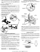
The hanger bars are designed for joists that are spaced 16” to 26” (center
to center) apart. If the joists are less than 16” apart, the hanger bars must
FIG. 2
1
st
Crease –
Bend Here
1
st
Notch –
Bend Here
be shortened to accommodate the narrower space. To shorten them:
“Male” Bar
“Female” Bar
4. Slide the “male” and “female” bars together and determine if the hanger
bar has been shortened enough. If not, separate the “male” and
“female” bars and break off additional material at the next crease and
notch. Continue to break off material until proper length is achieved. Do
not break off any more material than necessary.
5. Once proper length is achieved, separate the “male” and “female” bars.
Slide the “female” bars into the guides of the plaster frame. Slide the
“male” bars into the “female” bars.
1. Remove the hanger bars from the plaster frame. This may require
opening the guides of the plaster frame using pliers.
2. Spread the bars as wide as possible. (FIG. 2)
3. For each hanger bar, bend the “male” bar, back and forth at the 1
st
crease from the center until it splits. Bend the “female” bar, back and
forth, at the 1st notch from the center until it splits. (FIG. 2)
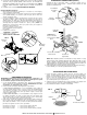
clips of the hanger bars cup underneath the
bottom edges of the joists. Hammer down
the nails of the hanger bars into the
joists to secure the assembly into
place. (FIG. 3 and FIG. 4)
CEILING JOIST INSTALLATION
1. Choose the location for the fixture, taking into consideration the required
7” clearance and the accessibility to the electrical supply.
2. Raise the housing/hanger bar assembly to the desired location between
the two ceiling joists. Adjust the width of both hanger bars to the
distance between the joists. Position the assembly so that the mounting
3. Slide the plaster frame along the hanger bars to the desired position.
Using pliers squeeze the guides of the plaster frame tightly around the
hanger bars to lock the position of the plaster frame.
4. Proceed to the “ELECTRICAL CONNECTIONS” section.
Nail
Mounting Clip
Hammer
Hanger bar
Joist
. FIG 4
FIG. 3
MODEL EVRH2000BA