
Instructions / Assembly

DROP CEILING INSTALLATION
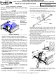
1. Choose the location for the fixture, taking into consideration the required
7” clearance and the accessibility to the electrical supply.
2. Install a ceiling tile onto the T-bar grid at the installation location. Using
the provided template and a keyhole saw make a hole at the desired
location in the ceiling tile.
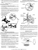
3. Place the housing/hanger bar assembly onto the ceiling tile into the
newly created hole. Adjust the width of both hanger bars to the distance
between the two T-bars, aligning each mounting clip with the top of its
corresponding T-bar. Press down on all mounting clips until they snap
onto the T-bar. (FIG. 5 and FIG. 6) NOTE: Holes are provided on the
mounting clips that can be used to secure the hanger bars to the T-bar.
Parts (I.e. screws, hex nuts) can be
purchased separately for this purpose.
4. Proceed to the “ELECTRICAL
CONNECTIONS” section.
5. Proceed to the “TRIM
INSTALLATION” section.
5. Install the insulation around the housing, if desired. Install the ceiling
material, such as drywall, over the housing. A template is provided to
assist in making the holes in the ceiling material. (NOTE: Blown-in
Insulation may also be installed after the ceiling material has been
installed.)
6. Proceed to the “TRIM INSTALLATION” section.
1. Using BX (armored) or NM (Romex) cable, run the supply wiring from the
power supply source to the fixture location. WARNING - Use supply
wires rated 90°C or higher.
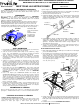
2. Open the hinged junction box’s door by lifting the metal latch.
A. FOR BX (ARMORED) CABLE - Break off one of the round knockouts
(FIG. 8) using a screwdriver. Secure an appropriately sized BX cable
connector to the knockout opening. Feed the BX cable through the
connector, providing 6” of slack inside the junction box. Tighten the
connector to secure the cable in place.
B. FOR NM (ROMEX) CABLE – Break off one of the rectangular
knockouts located on the top of the junction box using a screwdriver,
creating a slot. (FIG. 7) Slide the NM cable into the slot, as shown,
making sure there is 6” of slack inside the junction box. (FIG. 8)
3. Remove at least 3” of the cable’s outer sheath and remove the plastic or
paper over-wrap. Strip approximately 3/8” of insulation from the ends of
all supply wires. Using the provided “quick-connect” wire connectors,
make the following wire connections within the junction box:
WHITE Fixture Wire to WHITE (NEUTRAL) Supply Wire
BLACK Fixture Wire to BLACK (HOT) Supply Wire
GREEN Fixture Wire to GREEN / BARE (GROUND) Supply Wire
WARNING: First disconnect electricity at the circuit breaker or the fuse
box. Disconnecting power by using the wall switch is not sufficient to
prevent electrical shock.
ELECTRICAL CONNECTIONS
When using the “quick-connect” wire connectors, be sure that there are
no loose/exposed wire strands. Wrap each wire connection using UL
Listed electrical tape.
FIG. 7
Round
Knockout
ELECTRICAL CONNECTIONS (CONT.)
Flathead
Screwdriver
Pry out
knockout
FIG. 8
Junction
box door
Rectangular
Knockout
SLIDE-N-LOC™ -
Slide NM cable
into locking slot
NM Cable
(ROMEX)
“Quick-Connect”
wire connectors
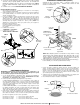
1. After installing and finishing the ceiling surface, insert the trim into the
housing. Insert the tip of a pencil into the loop of one of the coil springs.
Push the loop upward, stretching the coil spring, inserting the hook into
one of the keyhole slots locate on the socket plate. Repeat with the
remaining coil spring with the remaining keyhole slot to secure the trim in
place. (FIG. 9)
2. Screw a light bulb into the lamp socket and making sure to use the lamp
type an wattage specified on the housing’s lamp replacement label.
3. Installation is complete. Restore electrical power.
FIG. 9
4. Close the junction box door until the metal latch snaps, making sure that
all wiring and wire connectors are contained within the box.
Loop
Hook
Trim
Housing
Keyhole
Slot
NOTE: Additional lighting fixtures may be connected to the fixture’s
junction box. Several knockouts are provided on the junction box to
accommodate additional BX or NM cables intended to connect to other
fixtures. A marking on the junction box door specifies the maximum
number of wires and the maximum wire gauge that can be inserted into
the junction box.
TRIM INSTALLATION
Coil Spring
Mounting
Clip
T-bar
FIG. 5
Hanger
Bar
FIG. 6
ALL RIGHTS RESERVED. COPYRIGHT ENVIROLITE 2019