
Installation Guide

Super Bright Modular LED House Numbers
Directions for Installation
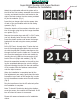
photo cell
Attach the end bracket without the photo cell to
the left of the rst number, assemble the numbers
in order, and attach the other end bracket to the
right of the last number. Use the screws provided
to join the modules. (Fig 1)
Insert the two hanger clips into the square slots
of each of the end modules with the tab facing
upwards. (Fig 2)
Select the location of the numbers. Mark the posi-
tion of the sign using the top the hanger brackets
as a guide. (Fig 3)
Make mark
Remove the number sign and drill 2 x 3/16” holes,
one inch directly below the top of the bracket.
Insert the plastic anchors and secure the hanger
brackets to the wall using the screws provided.
(Fig 4)
Drill a 3/8” feed - through hole 3” below the bot-
tom of the hanging bracket behind the end mod-
ule with the photocell. Feed the transformer wire
through the hole from the inside out. Connect the
wire from the transformer to the end module by
inserting the mini USB into the connector at the
back of the unit (Right side module). (Fig 2B)
Mount the assembled number to the wall by plac-
ing the completed address sign onto the hanger
clips and inserting the clips into the end modules
of the number. Slide the address number down
onto the clips to secure.
When the installation is completed and all the
nal adjustments are made, gently bend the tabs
forward on top of each of the hanger clip in order
to lock the address number onto the wall surface.
(Fig 5)
Plug the transformer into the AC outlet only after
the installation is complete.
Note: To check if functioning during the daytime,
cover the sensor; the number will illuminate. It will
turn off when the sensor is uncovered.
Please visit www.enviromate.com for installation
videos.
1”
3/16” holes
1” below
marks
(Fig 1)
(Fig 2)
(Fig 2B)
(Fig 3)
(Fig 4)
(Fig 5)