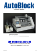
Operation Manual AutoBlock Serial Number: ________________________ Electrical Box Serial Number: ______________________ 490 Wando Park Blvd., Mt. Pleasant, South Carolina 29464 800-343-5319 or 843-881-6560 / Fax 843-881-3964 ENVEXP.
TABLE OF CONTENTS 4 4 4 Introduction What’s Included Uncrating Unpacking 5 5 5 6 6 6 7 7 7 8 8 Installation Preparing the AutoBlock lll Space & Weight Requirements Ventilation Front Door Installation Pump Compartment Door Installation Install Reagent Line Reagent Line Assembly Placement of Reagent Rack AutoBlock Reagent Port Install Drain Line & Carboy Electrical Box Installation page 9 10 System Overview Reagent Flow Path General Cleaning 11 11 12 12 13 Touch Screen Controller Main Screen Functions
TABLE OF CONTENTS 19 20 20 Run Mode Rack A / Rack B / Rack C Pause Button Main Screen Abort Button 21 21 22 22 22 22 23 23 23 23 24 24 25 Program Mode Heat Inject Wait Cool Pause Delete Open Save New Edit Import / Export Method Export Log Syntax Errors 26 27 27 30 Service Mode Setup Reagents Calibrate Temp Calibrate Pump Maintenance page 30 31 Options Supplies 32 Supplies List 33 Exit 34 34 34 34 34 Warranty 90-day Warranty 9-month Warranty Warranty Disclaimer Charges Not Covered by Warranty H
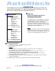
INTRODUCTION The AutoBlock has been designed specifically for your laboratory by providing safe, clean and efficient digestions. It is capable of digesting water, wastewater, soils, and other materials typically digested using hotplate chemistry.
INSTALLATION Preparing the AutoBlock Follow the instructions for uncrating from the quality control sheet supplied with the unit or introduction section of this manual. Follow the installation procedure step by step to insure proper function of the unit. Note: Residual water may be found in the internal plumbing of your AutoBlock. This includes the pump, reagent injection lines and drain lines. This water is non-hazardous, and was used for system check during quality control inspection.
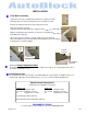
INSTALLATION Front Door Installation Unpack the front door assembly using caution not to scratch the acrylic. Both hinge pins have been inserted into the door assembly as shown. Remove the hinge pin from the left side using a hex wrench. Place door in cabinet opening, sliding the right side hinge pin into the cabinet location. Align the left side hinge pin location & screw in the second hinge pin. Hand tighten the hinge pin. Lift the door & close it. It will be a snug fit. Lift the door up & slide back.
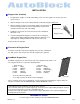
INSTALLATION Reagent Line Assembly 1. Cut appropriate lengths of 1/16”ID Teflon tubing, not to exceed 5’ lengths. The ends need to be a square-cut face. 2. Slide the flangeless nut over the tubing, with the nut threads facing the tubing end. 3. Slide the flangeless ferrule over the tubing, with the tapered portion of the ferrule facing towards the nut. The large diameter of the ferrule should be pushed to the end of the tubing. 4.
INSTALLATION Install Drain Line & Carboy • Remove the ½” barb fitting from the bag of parts supplied • Remove the nut from the fitting • Remove the cap from the carboy • Place the fitting into the cap. The treaded portion of the fitting needs to be on the inside of the cap. • Place the washer & then nut onto the fitting & tighten. • Place the cap back onto the carboy. carboy cap & bulkhead fitting • The drain line is located on the right side towards the back of the unit.
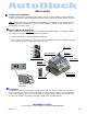
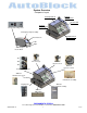
System Overview Component Layout Exhaust Compartment Lift Compartment Injection Arm Pumping Compartment Power module/ Voltage / Fuse Emergency Stop Assembly Graphite Block Compartment Touch Screen USB Stylus ABP164 on/off switch JC1 ABP125 lift sensors(3) JC2 ABP125 Inj arm sensor JC3 ABP152 pressure sensor electrical connections ABP127 leak detector sensor ABP128 exhaust fan assembly ABP130 RTD -Sample Assembly reagent ports ABP151 HEPA filter ENVIRONMENTAL EXPRESS For technical support ca
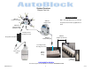
System Overview Reagent Flow Path General Cleaning ABP122 5-Valve Assembly Wipe clean with mild cleaner or isopropyl. ABP154 Pump Head Keep debris from inside of graphite block wells.
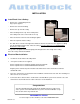
TOUCH SCREEN CONTROLLER The touch screen controller is specifically designed for use with the AutoBlock. Once the system is turned on, the AutoBlock software will automatically load. Pressing the screen tabs or input boxes with the attached stylus activates the touch screen. It is not necessary to push very hard, this may damage the screen. Manual Tab Main Screen Functions There are several operations that appear permanently on the touch screen.
TOUCH SCREEN CONTROLLER ABORT Abort Button If you need an emergency stop depress the E-STOP immediately. Emergency Stop Activate the ABORT By selecting the abort button, the abort operation will seize all communications to the control board. The temperature will not read correctly and will not heat. All motion is stopped. The ABORT button will turn green.
On Board Keyboard To activate this feature, select the icon on the task bar with the stylus. Typing -keyboard acts as any standard keyboard -press the SHIFT button to change the top row symbols/numbers -press the CAPS button to change from low/capital letters Move keyboard - Touch the keyboard and drag across the screen to new location.
START UP INSTRUCTIONS These start up instructions are to aid in optimizing the performance of AutoBlock. You system has gone through a quality control check during manufacturing. These parameters need to be checked at setup to ensure the system is in operable condition and the parameters meet your laboratory specifications. All parameters can be changed to meet your laboratory specifications.
START UP INSTRUCTIONS Sample Injection Tubing / Pump Calibration Follow the steps to Calibrate Sample Injection Tubing and Calibrate Pump under the Service Tab in this manual. The Sample Injection Tubing and Pump(s) has been tested and calibrated during manufacturing. It is best to calibrate the system again to ensure accuracy. Maintenance Review and set up the Maintenance portion under the Service Tab in this manual. The maintenance schedule has been set during manufacturing.
MANUAL TAB The manual mode is just what it implies. In this mode, digestion functions (raising/lowering racks, heating, cooling, injection, etc…) are performed individually by the analyst. The manual tab is used in method development, troubleshooting and on going inspections, and other situations where hands-on control of operations are required. Manual tab screen with dual system Rack Movement (yellow section) The (3) 18-position rack have been designed to hold 50ml vessels for a 54-well block.
MANUAL TAB HOME (blue section) This operation will home the three lift motors and the injection arm motor. The three lift motors will go to the down position and the injection arm will position itself over the drain. Press the Home button -A pop up message will appear: “HOME MOTOR?” Press Continue or Cancel button.
MANUALTAB Arm (red section) Select which column you would like a reagent injected to by the pull down menu -Select DRAIN, 9,8,7,….1 -Press the MOVE button -A pop up message will appear: “MOVE INJECTION ARM?”, Press Continue or Cancel button. Cancel You have canceled the command & return to the manual tab Continue The injection arm will move to the selected column A pop up message will appear: “INJECTION ARM MOVE COMPLETE.
RUN TAB The RUN TAB determines what methods will be selected and to what racks/columns they will be run. Run Tab Rack A / Rack B / Rack C After determining which rack(s) are going to be used, select the method you want to run. Some methods have been pre-programmed. Reference Program tab in the manual for adding/editing methods Load racks onto the lift arms in the down position NOTE: For proper airflow, all racks should be filled with empty cups. No need to run reagents in those columns.
RUN TAB Run Methods continued Continue The racks and the injection arm will home and the method will begin. Under the rack/method/column section, the screen will show which current command is being executed in the method. If syntax terror occurs The AutoBlock software will check for syntax errors in methods before starting -A pop up message will appear: “SYNTAX ERROR XX –method command line appears” -Look up syntax error in the PROGRAM TAB section of this manual.
PROGRAM TAB Methods are stored and can be edited. Custom methods can be programmed into the AutoBlock. Below depicts the Program Tab. Each command will be described in detail to ensure operator understanding. program mode –heat screen Program Tab HEAT Set the block temperature in 0C. Range: 150C to 1500C This is not sample temperature. Polypropylene cups can only be used to 1300C Command Sequence: 1. Select HEAT command from the main menu 2.
PROGRAM TAB WAIT Sets the amount of time the samples will be heated during a step. Range: 1-999 minutes. The method will wait for the set graphite temperature to be reached, ±50C degrees, rack are then lowered. The method will then wait for the specified number of minutes. program mode –wait screen Command Sequence: 1. Select WAIT command from the main menu 2. Select the wait time by up or down buttons or by keyboard. (minutes) 3. Added User Notes.
PROGRAM TAB EVERY METHOD At the end of each method the following two commands need to be added With the keyboard activated, press command area and type in the command string as follows: Press the CONTINUE button and SAVE the method enter: COLUMN DRAIN enter: DISPENSE H2O(1) 10 OPEN Opens directory where previous methods were saved MyComputer\LocalDisk(C)\HardDisk\Methods\ Select the OPEN button Select a method from the directory Press the OK button SAVE Save a new or edited method.
PROGRAM TAB IMPORT/EXPORT METHOD Methods are stored in this directory MyComputer\LocalDisk(C)\HardDisk\Methods\ Methods are saved by METHOD NAME.TXT file example: 200.7 WATERS 50ML.TXT Methods can also be written using notepad or word. Save as a text file (.txt) onto a USB stick Basic operator knowledge of Microsoft Windows is required Insert USB stick into USB slot near the touch screen IMPORT There are two ways to import methods 1.
PROGRAM TAB SYNTAX ERRORS Run Tab Select the method(s) and columns to run Press RUN METHODS button If there is an error in the method programming a popup will appear, note what syntax occurs syntax error will appear with the following format: SYNTAX ERROR# -COMMAND # definition and description 10 value out of range 20 unrecognized command 30 reagent not recognized 40 loop must execute at least 1 time 50 loop must use a stop loop command 60 elevator command must use up or down to specify location The method
SERVICE TAB The SERVICE TAB is set up for AutoBlock to be calibrated, maintained, and custom levels set for optimal performance. service tab screen Setup Reagents Select SETUP REAGENTS button from the SERVICE TAB Reagents are set to correspond with reagent ports. AutoBlock reagent ports are located on the left side of AutoBlock, labeled #’s 1-10.
SERVICE TAB reagent setup screen reagent new screen Setup Reagents continued • Selecting a different reagent on a port: -After selecting SETUP REAGENTS button from the SERVICE TAB use the pull down menu on the port by pressing the arrow button. -Select the reagent from the list. • To add a reagent to the pull down menu, you are able to add your own. Select the New button from the screen. A new screen will appear, input information needed.
SERVICE TAB Calibrate Temp The Graphite Block has been tested and calibrated during manufacturing to ensure a +/-2 0C variation in temperature range. The graphite block temperature needs calibration if a large variation is noted. Consult Environmental Express before calibrating. calibrate temp screen After selecting the Calibrate Temp button -A pop up message will appear: “DO YOU WANT TO CALIBRATE THE GRAPHITE BLOCK? YOUR OLD CALIBRATION TEMPERATUE WILL BE LOST.” Press Continue or Cancel button.
SERVICE TAB Calibrate Pump continued 6. After the reagent has injected 30ml. After the lines have injected, Move the ARM(red section) over the drain, by selection from the Column L drop down menu Press the MOVE button 7. Re-weigh each test tube and record the total weight (tube +H2O) 8. Average range is 2% • When the average range reaches 0-2%, you are ready to calibrate the pump(s).
SERVICE TAB manual screens Maintenance This section is designed to remind the operator when it is time for replacement of parts or calibration of processes. Failure to adhere to AutoBlock maintenance instructions and/or requirements can void all warranties and result in damage to the AutoBlock, loss of samples and/or losses not covered by the warranty. Please review the warranty section of this manual. After selecting the MAINTENENCE button, there are several items to be addressed on (3) pages.
SERVICE TAB Supplies Call Environmental Express for all your AutoBlock supplies. Have your AutoBlock serial number with you, this is located in the back of the unit and inside the exhaust compartment. After selecting the SUPPLIES button, Environmental Express contact information will appear. ENVIRONMENTAL EXPRESS 490 Wando Park Blvd. Mt. Pleasant, South Carolina 29464 Tel Tel Fax Email 800-343-5319 843-881-6560 843-881-3964 INFO@EnvExp.
Supplies Call Environmental Express for all your AutoBlock supplies. Have your AutoBlock serial number with you; this is located in the back of the unit and inside the exhaust compartment. ENVIRONMENTAL EXPRESS 490 Wando Park Blvd. Mt.
EXIT TAB EXIT Closes the program, shutting down the system and saving data Select the blue EXIT button in the center of the screen -A popup message will appear: “SAVING DATA BEFORE EXIT. THIS WILL TAKE A FEW MINUTES.” -Select the Continue button. When the AutoBlock software has finished exiting the top row of the screen will change ENVIRONMENTAL EXPRESS For technical support call 1-800-745-8218 or send email to INFO@ENVEXP.
Warranty The Environmental Express AutoBlock is warranted to heat, hold temperature, automatically add reagents, Warranty lift racks, cool samples with air flow and perform the stated functions of the touch screen controller for a period of ONE YEAR. This 1-year warranty is divided into two sections as follows: 90-Day Warranty The 90-day warranty covers parts, shipping and labor for a period of ninety (90) days from the original ship date, thereafter it expires.
Repair If your system requires attention beyond basic maintenance, please follow the guidelines below. Failure to so could result in loss of warranty protection and increased charges. Repair Approval Any attempt by laboratory personnel to repair the AutoBlock without first obtaining Environmental Express’ written consent may void all or part of the Warranty, expressed or implied. Call 800-343-5319 or (1-843-881-6560 outside the US) to obtain approval before beginning any repair work.