TABLE OF CONTENTS FOR YOUR SAFETY -------------------------------------------------- 1 SAFETY PRECAUTIONS -------------------------------------- 2 SPECIAL NOTES ON LCD MONITORS ------------------- 3 BEFORE YOU OPERATE THE MONITOR --------------------FEATURES -------------------------------------------------------PACKING LIST --------------------------------------------------INSTALLATION INSTRUCTIONS --------------------------CONTROLS AND CONNECTORS -------------------------ADJUSTING THE VIEWING ANGLE ------
Before operating the monitor, please read this manual thoroughly. This manual should be retained for future reference. FCC Class B Radio Frequency Interference Statement WARNING: (FOR FCC CERTIFIED MODELS) NOTE: This equipment has been tested and found to comply with the limits for a Class B digital device, pursuant to Part 15 of the FCC Rules. These limits are designed to provide reasonable protection against harmful interference in a residential installation.
PRECAUTIONS Do not use the monitor near water, e.g. near a bathtub, washbowl, kitchen sink, laundry tub, swimming pool or in a wet basement. Do not place the monitor on an unstable cart, stand, or table. If the monitor falls, it can injure a person and cause serious damage to the appliance. Use only a cart or stand recommended by the manufacturer or sold with the monitor. If you mount the monitor on a wall or shelf, use a mounting kit approved by the manufacturer and follow the kit instructions.
SPECIAL NOTES ON LCD MONITORS The following symptoms are normal with LCD monitor and do not indicate a problem. NOTES • Due to the nature of the fluorescent light, the screen may flicker during initial • • • • use. Turn off the Power Switch and then turn it on again to make sure the flicker disappears. You may find slightly uneven brightness on the screen depending on the desktop pattern you use. The LCD screen has effective pixels of 99.99% or more. It may include blemishes of 0.
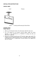
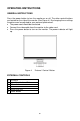
INSTALLATION INSTRUCTIONS SWIVEL BASE Install Figure 1 Remove Installing and Removing the Swivel Base POWER CORD Power Source: 1. Make sure that the power cord is the correct type required in your area. 2. This LCD monitor has an External universal power supply that allows operation in either 100/120V AC or 220/240V AC voltage area (No user adjustment is required.) 3.
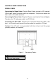
CONTROLS AND CONNECTORS SIGNAL CABLE Connecting the Signal Cable: Plug the Signal Cable one end to LCD monitor’s “DSUB-Input” socket, the other end to the computer's VGA port and tighten the two screws on the cable connector. Connecting the Power Cord: Plug the AC-power cord into the External Adapter. Then plug the DC-jack power cable into DC-IN Inlet. Connecting the DVI Cable: Connect one end of the 24-pin DVI cable to the back of the monitor and connect the other end to the computer’s DVI port.
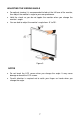
ADJUSTING THE VIEWING ANGLE • For optimal viewing it is recommended to look at the full face of the monitor, then adjust the monitor’s angle to your own preference. • Hold the stand so you do not topple the monitor when you change the monitor’s angle. • You are able to adjust the monitor’s angle from -5° to 20°. Figure 3 NOTES • Do not touch the LCD screen when you change the angle. It may cause damage or break the LCD screen.
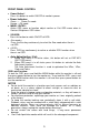
OPERATING INSTRUCTIONS GENERAL INSTRUCTIONS Press the power button to turn the monitor on or off. The other control buttons are located on the side of the monitor (See Figure 4). By changing these settings, the picture can be adjusted to your personal preferences. • The power cord should be connected. • Connect the video cable from the monitor to the video card. • Press the power button to turn on the monitor. The power indicator will light up. Figure 4 External Control Button EXTERNAL CONTROLS 1. 2. 3.
FRONT PANEL CONTROL • Power Button: Press this button to switch ON/OFF of monitor’s power. • Power Indicator: Green — Power On mode. Orange —Off mode. • MENU / ENTER : Active OSD menu or function adjust confirm or Exit OSD menu when in Contrast /Brightness OSD status. • SOURCE: Press this button to switch ON/OFF of DCR. • -/Eco mode : Press the Eco key continuously to select the Eco mode when there is no OSD . • +/DCR : Press DCR key continuously to active or disable DCR function when there is no OSD.
HOW TO ADJUST A SETTING 1. 2. 3. 4. Press the MENU-button to activate the OSD window (Figure 5). Press < or > to navigate through the functions. Once the desired function is highlighted, press the MENU-button to activate it. If the function selected has a sub-menu, press < or > again to navigate through the sub-menu functions. Once the desired function is highlighted, press MENU-button to activate it. Press < or > to change the settings of the selected function. To exit and save, select the exit function.
ADJUSTING THE PICTURE The descriptions for function control LEDS Main Menu Item Main Menu Icon Sub Menu Item Sub Menu Description Brightn ess Backlight Adjustment Contra st Contrast from Digital-register.
Main Menu Item Image Setup Main Menu Icon Sub Menu Item Sub Menu Description Clock Adjust picture Clock to reduce Vertical-Line noise. Focus Adjust Picture Phase to reduce Horizontal-Line noise H.Posit ion Adjust the verticalposition of the picture. V.Positi on Adjust the horizontal position of the picture. Warm Recall Warm Color Temperature from EEPROM. Normal Recall Normal Color Temperature from EEPROM. Cool Recall Cool Color Temperature from EEPROM.
Main Menu Item Color Boost Main Menu Icon Sub Menu Item Sub Menu Description Full Enhance on or off Disable or Enable Full Enhance Mode Nature Skin on or off Disable or Enable Nature Skin Mode Green Field on or off Disable or Enable Green Field Mode Sky-blue on or off Disable Mode or Enable Sky-blue AutoDetec Disable or Enable AutoDetect on or off t Mode Demo on or off Disable or Enable Demo Frame Size Picture Boost Adjust Frame Size Brightnes s Adjust Frame Brightness Contrast
Main Menu Item Main Menu Icon OSD Setup Sub Menu Item Adjust the verticalposition of OSD V.
Plug & Play DDC2B Feature This monitor is equipped with VESA DDC2B capabilities according to the VESA DDC STANDARD. It allows the monitor to inform the host system of its identity and, depending on the level of DDC used, communicate additional information about its display capabilities. The DDC2B is a bidirectional data channel based on the I²C protocol. The host can request EDID information over the DDC2B channel. THIS MONITOR WILL APPEAR TO BE NON-FUNCTIONAL IF THERE IS NO VIDEO INPUT SIGNAL.
TECHNICAL SUPPORT (FAQ) Problem & Question Possible Solution *Check if the Power Switch is in the ON position *Power Cord should be connected *Check if the PC system is Plug & Play compatible *Check if the Video Card is Plug & Play No Plug & Play compatible *Check if the D-15 plug pin of Video Cable is bent *Adjust the Contrast and Brightness Picture is fuzzy Controls. Picture bounces or a wave *Move electrical devices that may cause pattern is present in the picture electrical interference.
FOCUS adjusts the phase of the pixel clock signal. With a wrong phase adjustment the picture has horizontal disturbances in light picture. For FOCUS and CLOCK adjustment use “dot-pattern” or Win 95/98 shut-down mode pattern .
ERROR MESSAGE & POSSIBLE SOLUTION NO SIGNAL 1. Check that the signal-cable is properly connected , If the connector is loose, tighten the connector’s screws. 2. Check the signal-cable’s connection pins for damage. INPUT NOT SUPPORT Your computer has been set to unsuitable display mode ,set the computer to display mode given in the following table.
APPENDIX SPECIFICATIONS LCD Panel Driving system TFT Color LCD Viewable 558mm diagonal image size Pixel Pitch 0.282mm(H) × 0.282mm(V) Video Input R,G,B Analog Interface Digital Interface Separate Sync. H/V TTL H-Frequency 31kHz – 80kHz V-Frequency 56-75Hz Display Colors Dot Clock Max. Resolution 1680 x 1050@60Hz TM Plug & Play Power Consumption 16.
• • • • • • • • • • • • • • • Power Consumption (Maximum) Auto Adjust Button -/Eco mode DCR/+ Input Select Power Button MENU Luminance Image Setup Color Temp.
FACTORY PRESET TIMING TABLE STANDARD VGA SVGA XGA SXGA WXGA WSXGA RESOLUTION HORIZONTAL FREQUENCY VERTICAL FREQUENCY 640x480 31.469kHz 60 Hz 640x480 37.861kHz 72 Hz 640x480 37.500kHz 75 Hz 800x600 35.156kHz 56 Hz 800x600 37.879kHz 60 Hz 800x600 48.077kHz 72 Hz 800x600 46.875kHz 75 Hz 1024x768 48.363kHz 60 Hz 1024x768 56.476kHz 70 Hz 1024x768 57.515kHz 72 Hz 1024x768 60.023kHz 75 Hz 1280x1024 63.981kHz 60 Hz 1280x1024 79.976kHz 75 Hz 1280x960 60.
CONNECTOR PIN ASSIGNMENT 1 5 6 10 11 15 15 - Pin Color Display Signal Cable PIN NO. 1. 2. 3. 4. 5. 6. 7. 8. DESCRIPTION PIN NO. DESCRIPTION 9. 10. 11. 12. 13. 14. 15. +5V Detect Cable Ground DDC-Serial Data H-Sync V-Sync DDC-Serial Clock Red Green Blue Ground Ground R-Ground G-Ground B-Ground 24 - Pin Color Display Signal Cable PIN NO. DESCRIPTION PIN NO. 1. 2. 3. 4. 5. 6. 7. 8. 9. 10. 11. 12. TMDS Data 2TMDS Data 2+ TMDS Data 2/4 Shield TMDS Data 4TMDS Data 4+ DDC Clock DDC Data N.C.
ISO 14001 Certification ISO 14001 certification is the pattern of certification of the environmental management system, is the core standard of ISO14000 series of standard on environmental management.