Envision Series Air Handler Installation Manual Design Features Factory Options Accessories Dimensional Data Physical Data Performance Data Engineering Guide Specifications IM1603 07/08 WaterFurnace Air Handler
ENVISION SERIES AIR HANDLER INSTALLATION MANUAL Table of Contents Model Nomenclature. . . . . . . . . . . . . . . . . . . . . . . . . . . . . . . . . . . . . . . . . . . . . . . . . . . . . . . . . . . 2 General Installation Information . . . . . . . . . . . . . . . . . . . . . . . . . . . . . . . . . . . . . . . . . . . . . . . .3-9 Physical Data . . . . . . . . . . . . . . . . . . . . . . . . . . . . . . . . . . . . . . . . . . . . . . . . . . . . . . . . . . . . 3 Sizing Selection . . . . . . . . . . .
ENVISION SERIES AIR HANDLER INSTALLATION MANUAL Nomenclature
ENVISION SERIES AIR HANDLER INSTALLATION MANUAL General Installation Information tions in the literature, tags and labels attached to the unit and other safety precautions that may apply. Safety Considerations Warning: Before performing service or maintenance operations on a system, turn off main power switches to the equipment. Electrical shock could cause personal injury. Follow all safety codes. Wear safety glasses and work gloves.
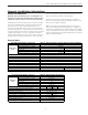
ENVISION SERIES AIR HANDLER INSTALLATION MANUAL General Installation Information Air Handler Sizing Selection The Envision Air Handlers are designed for R410a refrigerant and should be matched with Envision Split series compressor section according to the table below.
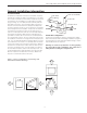
ENVISION SERIES AIR HANDLER INSTALLATION MANUAL General Installation Information Condensate Drain DS\b WT \SSRSR ! " >D1 1]c^ZW\U To facilitate condensate removal, the air handler should be pitched 1/4” towards the drain in both directions. The drain line contains cold water and should be insulated in unconditioned spaces to avoid drain line condensation from dripping on ceiling, etc. The drain pan has a primary and auxiliary drain connection.
ENVISION SERIES AIR HANDLER INSTALLATION MANUAL General Installation Information Bottomflow Application Horizontal Right Air Discharge Application To convert the NAH series air handlers for bottomflow applications follow the steps shown below: 1. Remove all access panels. Disconnect the blower harnesses from the motor and loosen ground wire from blower. Remove the blower by removing 2 screws from the blower mounting bracket, and slide the blower assembly out the front.
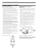
ENVISION SERIES AIR HANDLER INSTALLATION MANUAL General Installation Information Refer to the Refrigerant Line Sizing table to determine the proper line set configuration for the system being installed. Line sets over 60 feet in length are not recommended. If the line set is kinked or deformed and cannot be reformed, Air Handler Installation The air handler is attached to the shipping pallet with screws.
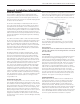
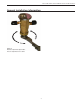
ENVISION SERIES AIR HANDLER INSTALLATION MANUAL General Installation Information 30 minutes after the adjustment is made for the system to stabilize. 3. Once the proper superheat setting has been achieved replace and tighten the seal cap. Warning – There are 8 total (360°) turns on the superheat adjustment stem from wide open to fully closed.
ENVISION SERIES AIR HANDLER INSTALLATION MANUAL General Installation Information Figure 4: Decrease Superheat: Open Valve Increase Superheat: Close Valve 9
ENVISION SERIES AIR HANDLER INSTALLATION MANUAL Hydronic Models The water heater and hydronic air handler must be located indoors and not subject to freezing temperatures. The water heater must be installed in accordance to local codes and its own installation instructions. The piping between the water heater and air handler should be kept to a minimum. Piping should be sized to allow for water velocities of 2’-4’ per second.
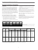
ENVISION SERIES AIR HANDLER INSTALLATION MANUAL Hydronic Models Water Presure Drop - Hydronic Coil Flow gpm Pressure Drop (PSI) 40°F 50°F 60°F 100°F 110°F 120°F 130°F 3.0 0.5 0.5 0.5 0.4 0.4 0.4 0.4 4.5 0.9 0.9 0.9 0.8 0.8 0.8 0.8 6.0 1.4 1.4 1.4 1.2 1.2 1.2 1.2 9.0 2.8 2.6 2.5 2.4 2.4 2.4 2.3 12.0 4.6 4.4 4.2 4.0 4.0 4.0 3.9 15.0 7.0 6.8 6.6 6.0 6.0 5.9 5.8 Coil Capacity vs.
ENVISION SERIES AIR HANDLER INSTALLATION MANUAL Electrical Data Model NAH 022 NAH 026 NAH 030 NAH 036 NAH 042 NAH 048 NAH 060 Electric Heat Capacity KW 240v BTUH 240v 0 4.8 0 4.8 0 4.8 9.6 0 4.8 9.6 0 9.6 14.4 14.4 0 16,382 0 16,382 0 16,382 32,765 0 16,382 32,765 0 32,765 49,147 49,147 0 9.6 14.4 14.4 0 32,765 49,147 49,147 0 9.6 14.4 14.4 0 32,765 49,147 49,147 19.2 19.
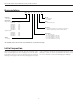
ENVISION SERIES AIR HANDLER INSTALLATION MANUAL Electrical Data Wiring Schematic 208-230/60/1 G Legend PB L1 Transformer Factory Low voltage wiring Factory Line voltage wiring Field low voltage wiring Field line voltage wiring Optional block DC Voltage PCB traces Internal junction Quick connect terminal T G Thermistor L2 Light emitting diode - Green 24V Red Gry(4) Brown Orange NOTE 1 Blue Relay coil Grn Capacitor w/ bleed resistor Yel Blk/Wh Switch - Condensate overflow P4 8 Wire nut
ENVISION SERIES AIR HANDLER INSTALLATION MANUAL Electrical Data Wiring Schematic Legend 208-230/60/1 208-230/60/1 Circuit 1 Circuit 2 G Factory Low voltage wiring Factory Line voltage wiring Field low voltage wiring Field line voltage wiring Optional block DC Voltage PCB traces Internal junction Quick connect terminal T G Thermistor L1 L2 L3 Note 4 L4 G PB L1 Transformer Light emitting diode - Green Red (2) L2 Black(3) Black Relay coil 24V Capacitor w/ bleed resistor Red BRK2 BR
ENVISION SERIES AIR HANDLER INSTALLATION MANUAL ECM Blower Control The ECM blower motor is controlled by an interface board installed in the air handler and allows field selectable CFM settings. The interface board receives inputs from the thermostat and converts them to signals used by the ECM motor. There are four different airflow settings that are field selectable via DIP switches (see Blower Performance table).
ENVISION SERIES AIR HANDLER INSTALLATION MANUAL Blower Performance Dip Switch Settings ;]RSZ $ ! !$ " "& $ A$ /cf 3[S`U ;]RS =\ =\ =TT =\ & ;Of 3A> eU 0Z]eS` ;]b]` V^ # =\ =\ ' # =TT =\ & # =\ =TT % # =TT =TT # =\ =\ # =TT =\ ' # % # "%# =TT %$ # =\ =TT & $ # " # =TT $% # =TT =TT %" #%# " # =\ =\ # '# $ =TT '%# %%# # =\ =\ #
ENVISION SERIES AIR HANDLER INSTALLATION MANUAL Unit Start Up • • • • • • • • • • • • • • • Check that supply voltage matches nameplate data. Fuses, breakers and wire size are correct. Low voltage wiring is complete. Piping is complete and water system is cleaned and flushed. Air is purged from the closed loop system. Isolation valves are open, water control valves or pumps are wired. Condensate line is open and correctly pitched. Transformer switched to 208v if applicable. DIP switches are set correctly.
ENVISION SERIES AIR HANDLER INSTALLATION MANUAL Dimensional Data Top Flow/Horizontal Unit Configuration B=> D73E @756B A723 D73E 4@=
ENVISION SERIES AIR HANDLER INSTALLATION MANUAL Dimensional Data Bottom Flow Unit Configuration B=> D73E 4@=
ENVISION SERIES AIR HANDLER INSTALLATION MANUAL Replacement Procedures Obtaining Parts When ordering service or replacement parts, refer to the model number and serial number of the unit as stamped on the serial plate attached to the unit. If replacement parts are required, mention the date of installation of the unit and the date of failure, along with an explanation of the malfunctions and a description of the replacement parts required.
Manufactured by WaterFurnace International, Inc. 9000 Conservation Way Fort Wayne, IN 46809 www.waterfurnace.com Product: Type: Size: Document: Envision Series - Air Handler Hydronic or R-410A 2-6 Tons Installation Manual WaterFurnace Renewable Energy has a policy of continuous product research and development and 7; $ ! % & reserves the right to change design and specifications without notice. ©2008 WRE.