NVISION NV3128 RS-422A Machine-Control Data Routing Switch Instruction Manual Manual Part Number: MN3128-00B
Printing History Model NV3128 Manual, Edition 2 Printed in the U.S.A. Copyright NVision, Incorporated January, 2000 July, 1993 All Rights Reserved No part of this manual may be reproduced in any form by photostat, microfilm, xerography, or any other means, or incorporated into any information retrieval system, electronic or mechanical, without the written permission of NVISION, Inc. Notice The information contained in this Operations Manual is subject to change without notice or obligation.
Warranty Statement NVISION, Inc. warrants that the equipment it manufactures shall be free from defects in materials and workmanship for a period of two (2) years, optionally extendable to five (5) years, from the date of shipment from the factory. If warranted equipment fails due to such defects, NVISION, Inc. shall, at its option, repair or provide replacement for the defective part or product.
Technical Support If you need support of any kind related to your equipment, contact the local representative who sold you the product, or you may contact NVISION, Inc. directly by any of the following methods. Telephone Main Telephone: (530)-265-1000 Technical Support: (530) 265-1059 Sales: 800-719-1900 or (530)-265-1000 Facsimile Main FAX Number: (530)-265-1010 Sales: (530)-265-1021 Email Technical Support: support@nvision1.com Sales: sales@nvision1.
Important Safeguards and Notices The information on the following pages provides important safety guidelines for both operator and service personnel. Specific warnings and cautions appear throughout the manual where they apply. Please read and follow this important safety information, especially those instructions related to the risk of electric shock or injury to persons.
Warnings A warning indicates a possible hazard to personnel which may cause injury or death. Observe the following general warnings when using or working on this equipment. - Heed all warnings on the unit and in the operating instructions. - Do not use this equipment in or near water. - This equipment is grounded through the grounding conductor of the power cord. To avoid electrical shock, plug the power cord into a properly wired receptacle before connecting the equipment inputs or outputs.
Cautions A caution indicates a possible hazard to equipment that could result in equipment damage. Observe the following general cautions when operating or working on this equipment. - When installing this equipment, do not attach the power cord to building surfaces. - To prevent damage to equipment when replacing fuses, locate and correct the problem that caused the fuse to blow before re-applying power.
North American Power Supply Cords The power cords supplied with this equipment have a molded grounding plug (NEMA 5-15P) at one end and molded grounding receptacle (IEC 320-C13) at the other end. Conductors are CEE colorcoded: Light blue (neutral), Brown (line) and Green or Green/Yellow (ground). Operation of this equipment at voltages exceeding 130 VAC will require power supply cords which comply with NEMA configurations.
TABLE OF CONTENTS 1. GENERAL INFORMATION ........................................................................................ 1-1 1.1 General .................................................................................................... 1-3 1.2 Architecture .............................................................................................. 1-4 1.3 I/O .......................................................................................................... 1-12 1.4 Physical .....
CHAPTER 1: GENERAL INFORMATION NV3128 RS-422A Machine-Control Data Switch 1-1
NV3128 RS-422A Machine-Control Data Switch 1-2
CHAPTER 1 - GENERAL INFORMATION 1.1 GENERAL The NV3128 is a serial digital switch for routing RS-422A machine-control data in a video or audio broadcast or production facility. Table 1.1 at the end of this section lists its performance specifications. Requiring only eight units of a 19" EIA rack for a bi-directional, 128-machine array, the NV3128 achieves a 10:1 space reduction over traditional analog or relay routers.
For very high reliability applications, a redundant controller can also be added to the frame, with circuitry provided for automatic changeover. With its duplex complexity, RS-422A has long been a troublesome method of plant signal routing. The NV3128 untangles the problems unique to this data type to offer an innovative, low-cost solution that merges easily into a facilitys over-all routing plan. A scaled-down version of the switch, with 64 of the 128 ports enabled, is available as model NV3128-64. 1.
NV3128 RS-422A Machine-Control Data Switch 1-5
Because commands are broadcast on one balanced pair and responses received on another, the systems crosspoint count, wiring density and complexity are inherently double that of a video or audio router. Fig. 1.2 shows the twolevel connection required to implement a route through a conventional data switch.
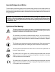
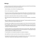
To further complicate matters, the sense of transmit and receive connections in many modern machines is switchable. That is, internal circuitry within the machine reassigns the interface pin assignments to allow it to operate in either controlled or controlling mode. Fig. 1.3 illustrates the physical pin swapping within each of two directly connected devices. On most units the changeover is a physical switch, but on some, such as the Sony D1 VTR, the pin flip is under software control.
Video equipment offers a sufficient diversity of control options to add another layer of complexity to routing. The Sony BVU machines have a single D connector for both controlling and controlled traffic. The direction of data traffic is controlled by the remote switch. The Sony BETA machines hard wire two D connectors together, again for both controlled and controlling traffic.
DYNAMIC PORTS The power of the NV3128 as a data router begins with its singular ability to dynamically configure each of its 128 I/O ports to one of three states: controlling, controlled or high impedance. Executed automatically with each take command, this transparent changeover action in the router emulates the mode-swapping capability of the external machines. It simultaneously simplifies a system and expands its overall capability. Fig. 1.4 illustrates this essential circuit function.
CROSSPOINT ARCHITECTURE Figure 1.5 is a simplified representation of the interface between the I/O connectors, the dynamic ports, and the crosspoint matrix. The crosspoint matrix itself consists of four LSI 64x64 crosspoint chips connected in a unidirectional 128x128 m by n architecture. In this non-blocking scheme, any of the 128 inputs can be switched to any of the 128 outputs. Each output is controlled by a double-buffered register with a load and an active segment.
NV3128 RS-422A Machine-Control Data Switch 1-11
MULTIDROP COMMAND CHAINS Gating off the response transmitter in a controlled port is an effective and transparent technique to resolve bus contention in a multi-drop command chain. In such a mapping, the controlling device sends commands to multiple destinations, but only one destination is allowed to respond. All other controlled-port transmitters are gated off.
1.5 ANCILLARY EQUIPMENT The NV3128 operates in a sophisticated audio/video environment, typically supporting a mix of modern digital equipment and older analog gear. To facilitate the integration of this diverse machinery, NVision has developed a wide and growing family of ancillary products including the NV1000 series processing equipment and the NV4000 series.
TABLE 1-1 NV3128 SPECIFICATIONS INPUTS/OUTPUTS Number NV3128-128 NV3128-64 Protocol Input Impedance Input Range Output 128 64 RS-422A, Balanced ,9-PinD Connector, Dynamically configured as controlled or controlling 100 ohms 200mV to 10V p-p 7V p-p, Low Impedance PERFORMANCE Control Update RS-422A Data Rate 100% remap of switch < 16 mSec. 5MBits/sec. NRZI maximum MECHANICAL Frame Dimensions 8 EIA rack units, aluminum 356mm W x 483mm H x 381mm D (14" x 19" x 15") 20.5 Kgs. (45 Lbs.
CHAPTER 2: INSTALLATION NV3128 RS-422A Machine-Control Routing Switch 2-1
NV3128 RS-422A Machine-Control Routing Switch 2-2
CHAPTER TWO - INSTALLATION CAUTION: THE FOLLOWING INSTALLATION PROCEDURES ARE INTENDED FOR QUALIFIED SERVICE PERSONNEL ONLY. TO REDUCE THE RISK OF ELECTRIC SHOCK, DO NOT PERFORM ANY SERVICING OTHER THAN THAT CONTAINED IN THE OPERATING INSTRUCTIONS UNLESS YOU ARE QUALIFIED TO DO SO. REFER ALL INSTALLATION AND SERVICE TO QUALIFIED PERSONNEL. 2.1 HARDWARE INSTALLATION The following discussion makes frequent reference to Fig 2.1 The NV3128 installs in a 19-inch EIA equipment rack.
8. Connect the AC line cord at the rear of the frame and to the input AC, which powers up the NV3128. Ensure the system powers up correctly. a. LEDs on the Power Supply front panel should glow. b. Measure the voltages at the DC tespoints on the Power Supply. The value should be within +/- 1VDC of the value silkscreened at the test point. (If no boards are plugged in, the voltages will be very high, around ±9 and ±20 volts.) 9. Disconnect the AC line cord(s) from the PS2001 power supply(ies).
FIGURE 2.
2.2 CONFIGURATION 2.2.1 THE UNIVERSAL CONTROL OR COMMAND INTERPRETER The Universal Control Card (EM0134-XX) constitutes the current control module for the NV3128 Router. It includes a Test/Normal jumper near the front of the card that should always be set to Normal mode. In addition there are two AES Ref jumpers that are not used in the NV3128. Partitioning, port configuration, and diagnostic interface settings are done using the UniDiag PC software program. See the UniDiag Manual for instructions.
PARTITION DIP SWITCHES (OBSOLETE) 1. Two banks of dip switches on the Control Interface Module configure the partition information for the NV3128. Bank 1 defines the physical partition, Bank 2 enables the ghost partition and defines its controller level. BANK 1 SECT A S293 BANK 1 SECT B S290 BANK 2 SECT A S285 BANK 2 SECT B S247 The bit settings are discussed on the following pages. X denotes "don't care" setting.
SETTINGS: ENABLE (s8): ON: Partition defined in switchbank is enabled. OFF: Partition is disabled. RE-INITIALIZE BIT/MULTIDROP ENABLE (s7): OFF: On power-up following a shutdown of less than twenty minutes, the system restores the crosspoint address map stored in batterypowered RAM. In Bank 2, when bit 7 is OFF, multidrop is disabled and point to point routing is enabled in the second partition.
INPUT LENGTH (s8-s5): Bit 8 (MSB) through bit 5 (LSB) of the B switch section create a fourbit binary, modulo 32 number that matches the input dimension of the switch. The length of the partition is the number in the switch times 32. For the NV3128, the number is 0100 (128). For a 64 port version of the switch, the number is 0010. No other configuration is valid for a data switch. EXAMPLE: 0100 (decimal 128) = an input address range of 128 consecutive physical addresses.
2.2.4 CONFIGURING THE SERIAL INTERFACE (OBSOLETE) 2.2.4.1 JUMPER SETTINGS (OBSOLETE) The serial data interface between the control system and the NV3128 can be either RS-422A or RS-232. For the newer Universal Control module, the serial interface ports are set up using UniDiag. For the older Command Interpreter, jumpers on the Command Interface Module select parameters appropriate to the chosen protocol.
2.2.5 PARALLEL INTERFACE (OBSOLETE) Newer NV3128 frames do not include a parallel interface. The older NV3128 frames with the Command Interpreter card included a parallel connector which could be used with the Pesa parallel interface. Because the Universal Control card does not support the parallel interface, older frames that have the Universal Control card cannot make use of the parallel interface connector. 2.2.
Additionally, two jumpers float or ground pins 5 and 9 of interface connector J40 for further configuration flexibility.
2.2.7 CONFIGURING THE REFERENCE INPUT The NV3128 can derive its timing from a Video Reference input, or it can free run. The reference input is normally a video black burst signal, but optionally can be an AES/EBU digital audio bitstream. Both video and audio reference inputs require that their connection end-points be terminated in the cables characteristic impedance to avoid line reflections.
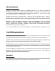
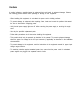
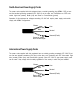
2.3 CABLING THE NV3128 Figures 2-2 and 2-3 at the end of this section show the rear panel connections on the NV3128. Notice that there are old and new frames corresponding to the old Command Interpreter and the new Universal Control Card. 2.3.1 DATA I/O Machine control I/O connections to the rear panel are straightforward. D connectors terminated according to the following pin-out are plugged into any of the 128 terminals provided. 2.3.
RS-422 Cable Pin-Out PIN Controlling Device Controlled Device 1 Frame Ground Frame Ground 2 Receive A Transmit A 3 Transmit B Receive B 4 Transmit Common Receive Common 5 Spare Spare 6 Receive Common Transmit Common 7 Receive B Transmit B 8 Transmit A Receive A 9 Frame Ground Frame Ground NV3128 RS-422A Machine-Control Routing Switch 2-15
RS232 (OBSOLETE): The NV3128 Control/Command Interpreter interface is always a DCE device when operating in RS-422A mode. As shown above, the system can be configured as either DTE or DCE equipment in RS-232 mode. It should be noted, however, that the selection of DTE or DCE involves only the exchange of pins 2 and 3 at one end of the interconnecting cable. The exchange can be made in the cable, or on the controller board.
OPTION II: If the controlling RS232 device communicates over a 25pin serial port: 1. Configure the Control Interface Module as a DTE 2. Create (or buy) a 9-pin (male) to 25-pin (female) cable using the 9-pin to 25-pin RS-232 wire list below. 9-PIN CONNECTOR 25-PIN CONNECTOR 1 8 2 3 3 2 4 20 5 7 6 6 7 4 8 5 9 22 OPTION III: If the controlling RS232 device communicates over a 9-pin serial port: 1. Configure the Control Interface Module as a DCE. 2.
2.4 ADDING A REDUNDANT CONTROLLER A second Universal Control/Command Interpreter can be specially ordered and installed for increased system reliability. If you have the Universal Control card, you must also have the Universal Control frame in order to install a redundant control card. Contact Technical Support to verify that your frame can accept a redundant controller. To install: 1. Remove the existing Universal Control/Command Interpreter from the frame. 2.
2.6 PC DIAGNOSTIC INTERFACE (UNIDIAG/NVUTILS) NVision furnishes a configuration and diagnostic computer utility with the routing switch. For newer systems having the Universal Control Card, the program is called UniDiag. For older systems having the Command Interpreter, the collection of programs is called NVUtils or RouterDiag. The program(s) run on a PC compatible computer.
LOOP THRU CTL1 CTL2 LOOP THRU REF 1 REF 2 ETHER NODE CTL1 CTL2 BUS NET RS-422 SECONDARY CTL RS-422 PRIMARY CtL RS-232 MEZ DIAG RS-232 DIAG ALARMS VIDEO VIDEO CONTROL SYSTEM CONNECTORS UNIDIAG REAR CONNECTOR VIDEO REF INPUTS 1 & 2 MACHINE CONTROL CONNECTORS 1 - 128 FIG 2-2.
FIG FIG2-2. 2-3.
2.4 PC-BASED SOFTWARE INSTALLATION (OBSOLETE) IMPORTANT NOTE: The remainder of this section applies only to older systems using the Command Interpreter module. For newer systems using the Universal Control Card, skip the remainder of this section and go to the UniDiag manual. GENERAL NVUtils is a collection of PC compatible computer programs that provide diagnostics and control of the NVision family of digital routing switches. The utilities currently consist of two programs, NVTake and NVMap.
SOFTWARE INSTALLATION FIXED DISK A. Create an NVUtil subdirectory for the program and its map data. B. Change Directory to the NVUtil subdirectory. C. Copy the program files from the supplied diskette. D. Create a batch file to invoke each program. The batch files should exist in a directory within the computers command search environment. Each batch file shall first position the computer in the NVUtil subdirectory, then invoke the desired program.
OPERATION FROM A FLOPPY DISK A. Copy the program files supplied to a blank floppy. B. Invoke either program from the floppy. Edited map, config and salvo files will be saved to the floppy in the course of the program session. C. Remove the floppy and store it safely. HARDWARE CONFIGURATION A. Refer to "Configuring the Diagnostic Interface" earlier in this section to configure the diagnostic interface for RS-232 operation.
CHAPTER 3: OPERATION NV3128 RS-422A Machine Control Data Routing Switch 3-1
NV3128 RS-422A Machine Control Data Routing Switch 3-2
CHAPTER 3 - OPERATIONS The NV3128 requires no operator intervention. The router may be controlled completely via the selected control system. Section 3.1 discusses the connection algorithms for point-to-point (Level I) and multidrop (Level II) Takes issued by the control system to control the router. Section 3.2 covers the computer-based management unilities. 3.
On older systems, DIP switches on the Command Interpreter establish the logical ID for each of the two levels and also configure the partition parameters. On newer systems with the Universal Control module, levels and partitions are set up using UniDiag. 3.1.1 POINT-TO-POINT CONNECTION RULES: 1. If Requested Destination is in use as a source: Find all destinations, break connections and tristate (turn off) the ports. 2.
3.2 COMPUTER UTILITIES (OBSOLETE) The following information applies only to older systems with the Command Interpreter module. Newer systems with the Universal Control module use UniDiag instead of the NVUtils described below. See the UniDiag manual for details. NVUtils is a collection of PC compatible computer programs that provide diagnostics and control of the NVision family of digital routing switches. The utilities currently consist of two programs, NVTake and NVMap.
3.2.1 OPERATING INSTRUCTIONS - NVTAKE (OBSOLETE) INVOCATION: NVTAKE [H | U | V | E | R] [1|2] [9600|38400] Where argument 1 is the router control protocol from the following list: H = Horiz on control protocol U = Utah Scientific V = Vistek E = ESBus R = BTS and argument 2 is the communications port, default = COM1. Argument 3 is the serial portss baud rate. Default = 9600 Invoking NVTAKE with no arguments displays the programs syntax summary. Figure 3.1 illustrates the basic NVTake screen.
F1 SENDING A SINGLE TAKE The F1 function key enters the single-take mode of operation. The cursor moves to the source address prompt in the upper left hand corner of the screen. When source and destination addresses have been entered, the take is sent to the routers Control Interface. A results message is displayed on the lower right-hand portion of the screen, either COMMAND COMPLETED or TIME OUT, NO RESPONSE.
F9 - BUILD A SALVO TABLE The F9 function key initiates building or editing a take salvo. The cursor position prompts source and destination address fields. Keyboard arrows move around the list. A single source may be connected to multiple destinations in the salvo, but when multiple sources are connected to a single destination, the last entry over-rides any predecessor. ESC ends the table-editing session. The program asks whether or not to save the table to disk.
F10 - LOAD A SALVO FROM DISK The F10 function key loads a file from the current directory from which NVTAKER was launched. The program asks for the name of the file defining the salvo. Enter the name with no extension. F2 - SEND A SALVO The F2 function key sends the salvo information currently in the computers memory to the control interface. A results message is displayed on the lower right-hand portion of the screen, either COMMAND COMPLETED or FAILED.
QUERYING SYSTEM CONNECTIONS (VISTEK PROTOCOL ONLY) F4 - QUERY A SINGLE CROSSPOINT The F4 function key enters the single-crosspoint query mode. The cursor is positioned on the destination address field. Upon entry of the destination field, the source address connected to that destination will be returned in the Source Address field. F5 - QUERY MULTIPLE CONNECTIONS The F5 function key enters the multiple-crosspoint query mode. The cursor is positioned on the Destination Address field.
3.2.2 OPERATING INSTRUCTIONS - NVMAP (OBSOLETE) INVOCATION: NVMAP [H | U | V | E | R] [1|2] Where argument 1 is the router control protocol from the following list: H = Horiz on control protocol U = Utah Scientific V = Vistek E = ESBus R = BTS and argument 2 is the communications port, default = COM1. Invoking NVMap with no arguments displays the programs syntax summary. OPERATION: NVMap operates from two screens.
NV3128 RS-422A Machine Control Data Routing Switch 3-12
Screen I Query crosspoint connections: 1. Enter the number of the lowest output port you want to query 2. The screen will display the connections made to the first 16 output ports starting with the address entered. Query output monitor connections: 1. Depress function key F3 2. The state of the output monitor connections is displayed in the upper right-hand corner of the screen. Diagnostic messages: Diagnostic messages are sent to screen I continuously.
Screen II Editing the scramble map: 1. Function Key F7 allows setting the router level on which the scramble map is to operate. ESC exits this edit mode. 2. Function key F2 loads the scramble map currently active in the router controller RAM. 3. Function Key F3 loads a scramble map previously saved to disk. 4. Function key F8 invokes the scramble map editor. 5. Function key F4 downloads the edited scramble map, along with the configurationinformation entered in screen I, to the router. 6.
CHAPTER 4: THEORY OF OPERATION NV3128 RS-422A Machine-Control Data Routing Switch 4-1
NV3128 RS-422A Machine-Control Data Routing Switch 4-2
CHAPTER FOUR - THEORY OF OPERATION 4.1 SYSTEM Fig 1.5 is repeated here to demonstrate the bidirectional flow of data through the routing switch. The illustration shows a controlling machine sending and receiving data through a controlled port on the router. Two crosspoints enable the forward and reverse data paths through the switch. A controlled machine receives and answers this command traffic through a controlling port. 4.1.
NV3128 RS-422A Machine-Control Data Routing Switch 4-4
4.2 CIRCUIT OPERATION The following discussion provides an overview of circuit operation for each of the circuit boards in the NV3128 Router frame. Because repair is done by replacing modules rather than repairing them, schematics and bills of material are not provided but may be requested from NVISION Technical Support. 4.2.1 I/O CONNECTOR INTERFACE ASSY: EM0038-XX RS-422A Machine Control data enters the NV3128 through PCmounted D connectors on this passive connector interface assembly.
4.2.3 CROSSPOINT MODULE: ASSY EM0041-XX INPUT DATA Input signal data flows into the crosspoint module from the signal backplane. The data is resistor coupled into buffer/driver integrated circuits, then passed onto the data bus for application to the crosspoint ICs. Control data from the Command Interpreter arrives through the backplane and into a similar circuit.
4.2.4 I/O ASSEMBLY: EM0040-XX The I/O module is a bidirectional interface between the router's crosspoint matrix and the external machines. Two modules, each supporting 64 ports, make up the full complement of I/O circuits. The assembly plugs simultaneously into both backplanes, communicating with the crosspoint module through the Signal Backplane and with the external machines through the I/O Backplane. A total of 64 proprietary receiver/driver submodules pass data to and from the I/O backplane.
4.2.5 UNIVERSAL CONTROL/COMMAND INTERPRETER MODULE ASSY: EM0127-XX, EM0134-XX, EM0035-XX The following discussion refers to both the Universal Control and Command Interpreter modules. Although these modules use different designs, they are functionally very similar. The Universal Control/Command Interpreter Module receives take commands from an external controller and reformats them for use by the Crosspoint Module.
ASYNCHRONOUS TIMING Asynchronous system timing consists of two signals. The first, derived from the reference video inputs re-trace interval, activates the pre-loaded information in the crosspoints double-buffered registers. This action executes a take. The second timing signal is a system master clock. A sync stripper derives the vertical retrace pulse and passes it on to a microprocessor for processing into strobe and write-enable signals. An oscillator provides the master clock for the entire system.
4.2.5 POWER SUPPLY ASSY: PS2001-XX The NV3128 Frame and its Power Supply are UL listed. The Power Supply Module PS2001-01 powers the NV3128 from the AC line at a nominal voltage of 115 VAC - 60 Hz or 230 VAC - 50Hz. The power supply is designed to accept input voltages in the range of 88 VAC to 135 VAC, or 210 VAC to 270 VAC and to provide DC outputs of +17V, -17V, +7V, and -7V. AC Power enters the system through connectors mounted on the rear panel.
Metal oxide varistors DV1 and DV2 clamp voltage spikes on the AC input lines to safe levels. Further, the PS2001 automatically bleeds all input capacitors when the unit is removed from the frame. Normally, a diode is connected to ground through the backplane, biasing FET Q4 off. Upon removal of the module from the frame, the FET conducts, quickly discharging the capacitors, thus minimizing the chance of electrical shock. Switching FETs Q1 and Q2 chop the high voltage DC at 40 kHz into a square wave.
NV3128 RS-422A Machine-Control Data Routing Switch 4-12
CHAPTER 5: MAINTENANCE AND TROUBLESHOOTING NV3128 RS-422A Machine Control Data Routing Switch 5-1
NV3128 RS-422A Machine Control Data Routing Switch 5-2
CHAPTER 5 - MAINTENANCE AND TROUBLESHOOTING 5.1 CUSTOMER SUPPORT Nvision customer support is available Monday through Friday during normal business hours, Pacific Standard Time (PST). The customer support telephone number is (530) 265-1000. For additional information, see Technical Support at the front of this manual. 5.2 SCHEDULED MAINTENANCE The NV3128 requires no periodic maintenance.
5.4 TROUBLESHOOTING Certain features of the NV3128 facilitate troubleshooting the router. · Power supplies and all active modules can be removed and re-inserted live without damage. · Since mapping of the crosspoint modules takes place continuously, a crosspoint card removed and re-inserted will be updated within a few cycles of video vertical retrace. · Removing the Universal Control/Command Interpreter will not upset the switch mapping.
SIGNAL PATH The quickest way to isolate problems in a single connection is by module substitution. If sufficient spares are not available to carry out this strategy, the next best recourse is path substitution: 1. Route the problem signal to a new crosspoint/output address. 2. If new route does not correct the problem, the source port circuitry is probably faulty. Verify by reconnecting the source machine to a new port, or by swapping the two I/O modules.
NV3128 RS-422A Machine Control Data Routing Switch 5-6
GLOSSARY NV3128 RS-422A Machine-Control Data Routing Switch G-1
NV3128 RS-422A Machine-Control Data Routing Switch G-2
GLOSSARY AES/EBU ......................................... Audio engineering Society/European Broadcast Union ATR .................................................. Commonly used abbreviation for Audio Tape Recorder Audio ............................................... Sound element of a television program, composed of one or more channels of sound, music, and narration Bi-phase .......................................... Data encoding format for serial transmission Cue audio ................................
MOV ................................................. Abbreviation for Metal Oxide Varistors MUX ................................................. Commonly used abbreviation for Multiplexer Board Nm ................................................... Nanometer - metric measurement, refers to frequency of fiber optic spectrum NTSC ............................................... National Television Systems Committee.
VCXO ............................................... Voltage Controlled Crystal Oscillator VDE .................................................. Verband Deutscher Electrotechniker Video ............................................... Picture element of a television signal VTR ..................................................
NV3128 RS-422A Machine-Control Data Routing Switch G-6
INDEX NV3128 RS-422A Machine-Control Data Switch Index-1
NV3128 RS-422A Machine-Control Data Switch Index-2
Index A Ancillary Equipment 1-13 Architecture, System 1-4 ATR G-3 Audio G-3 B Backplane (theory) 4-5 Bi-phase G-3 C Cabling 2-14 Circuit Theory 4-5 Command Interface, Connecting 2-14 Command Interpreter 2-6 Configuration 2-6 Connection Notes 3-3 Control Module (theory) 4-8 Control Structure (Theory) 4-3 Crosspoint Module (theory) 4-6 Cue audio G-3 Customer Support 5-3 D D1 G-3 D2 G-3 DAC G-3 Delta-Sigma techniques G-3 Diagnostic Interface 2-19 Diagnostic Interface, Configuring Duplex G-3 Dynamic Ports 1-
H HDTV G-3 HDVS G-3 Hybrid G-3 I I/O G-3 I/O Assembly (theory) 4-7 I/O Interface Modules 4-5 IC G-3 Installation, Hardware 2-3 J Jumper and Switch Settings 2-6 Jumper J1 - 115/230 VAC 4-10 L LED G-3 M Maintenance 5-3 Monaural G-3 MOV G-4 MUX G-4 N Nm G-4 NTSC G-4 NVMAP 3-5 NVTAKE 3-5 O Operating Instructions, NVMAP 3-11 Operating Instructions, NVTAKE 3-6 Oversampling G-4 P PAL G-4 Parallel Interface 2-11 Partitioning 2-6 Power Supply (theory) 4-10 PROM G-4 PWM G-4 R RAM G-4 Redundant Controller 2-18
S S/N G-4 Safeguards and Notices Front-5 Serial Interface, Configuring 2-10 Simplex G-4 SMPTE G-4 Software Installation 2-22 Specifications 1-14 ST type connector G-4 Stereo G-4 Stereo pair G-4 STLs G-4 Switcher G-4 Symbols and Their Meanings Front-5, Front-6 Synchronization G-4 System Overview 4-3 T Technical Support Front-4 Troubleshooting 5-4 TTL G-4 U Universal Control 2-6 Utilities, PC Computer 3-5 V VCXO G-5 VDE G-5 Video G-5 VTR G-5 W Warranty Statement Front-3 Y Year 2000 Warranty Statement F
NV3128 RS-422A Machine-Control Data Switch Index-6