EN9110 EN9110 19” LCD Monitor User’s Manual By Envision Peripherals, Inc. www.envisionmonitor.
EN9110 Before operating the monitor, please read this manual thoroughly. This manual should be retained for future reference. FCC Class B Radio Frequency Interference Statement WARNING: (FOR FCC CERTIFIED MODELS) NOTE: This equipment has been tested and found to comply with the limits for a Class B digital device, pursuant to Part 15 of the FCC Rules. These limits are designed to provide reasonable protection against harmful interference in a residential installation.
EN9110 PRECAUTIONS ! Do not use the monitor near water, e.g. near a bathtub, washbowl, kitchen sink, laundry tub, swimming pool or in a wet basement. ! Do not place the monitor on an unstable cart, stand, or table. If the monitor falls, it can injure a person and cause serious damage to the appliance. Use only a cart or stand recommended by the manufacturer or sold with the monitor. If you mount the monitor on a wall or shelf, use a mounting kit approved by the manufacturer and follow the kit instructions.
EN9110 PRECAUTIONS (cont) • For maximum protection, repackage your monitor as it was originally packed at the factory. • To keep the monitor looking new, periodically clean it with a soft cloth. Stubborn stains may be removed with a cloth lightly dampened with a mild detergent solution. Never use strong solvents such as thinner, benzene, or abrasive cleaners, since these will damage the cabinet. As a safety precaution, always unplug the monitor before cleaning it.
EN9110 SPECIAL NOTES ON LCD MONITORS The following symptoms are normal with LCD monitor and do not indicate a problem. NOTES • Due to the nature of the fluorescent light, the screen may flicker during • • • initial use. Turn off the Power Switch and then turn it on again to make sure the flicker disappears. You may find slightly uneven brightness on the screen depending on the desktop pattern you use. The LCD screen has effective pixels of 99.99% or more. It may include blemishes of 0.
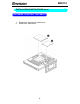
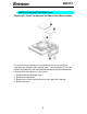
EN9110 INSTALLATION INSTRUCTIONS INSTALLATION INSTRUCTIONS SWIVEL BASE Install Figure 1 Remove Installing and Removing the Swivel Base POWERCORD Power Source: 1. Make sure that the power cord is the correct type required in your area. 2. This LCD monitor has an External universal power supply that allows operation in either 100/120V AC or 220/240V AC voltage area (No user adjustment is required.) 3.
EN9110 INSTALLATIONS INSTRUCTIONS (cont) PREPARING TO INSTALL THE CABLES 1. 2. Remove the wall mounting hole cover. Remove the cable cover.
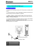
EN9110 INSTALLATIONS INSTRUCTIONS (cont) CABLE CONNECTIONS 1 – Connect the DC-jack power cable into DC-IN connector on the back of the monitor. 2. Connect one end of the 15-pin D-Sub cable to the back of the monitor and connect the other end to the computer’s D-Sub port. 3. (Optional – Requires a video card with DVI port) Connect one end of the 24-pin DVI cable to the back of the monitor and connect the other end to the computer’s DVI port. be tightened.
EN9110 INSTALLATION INSTRUCTIONS (cont) Preparing To Install The Optional Wall Mount Arm (Not Included) CONNECTIONS This monitor can be attached to a wall mounting arm you can purchase separately from Ergotron (www.ergotron.com). Turn the power OFF then disconnect the cables from the monitor before performing the procedure below. Lay the monitor face down on a soft surface. 1. 2. 3. 4. Remove wall mounting hole cover. Remove the cable cover. Remove the 4 screws holding the base to the back of the monitor.
EN9110 INSTALLATION INSTRUCTIONS (cont) Attaching The Optional Wall Mount Arm (not supplied) Follow these steps to finish installing the wall mounting arm: 1. 2. 3. Place the wall mounting arm onto the back of the monitor. Line up the holes of the arm with the holes in the back of the monitor. Insert the 4 screws into the holes and tighten. Reconnect the cables. Refer to the user’s manual that came with the optional wall mounting arm for instrucstions on attaching it to the wall.
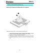
EN9110 ADJUSTING THE VIEWING ANGLE INSTALLATION INSTRUCTIONS • For optimal viewing it is recommended to look at the full face of the • • monitor, then adjust the monitor’s angle to your own preference. Hold the stand so you do not topple the monitor when you change the monitor’s angle. You are able to adjust the monitor’s angle from -5° to 20°. Figure 3 NOTES • Do not touch the LCD screen when you change the angle. It may cause • damage or break the LCD screen.
EN9110 OPERATING INSTRUCTIONS GENERAL INSTRUCTIONS Press the power button to turn the monitor on or off. The other control buttons are located on the side of the monitor (See Figure 4). By changing these settings, the picture can be adjusted to your personal preferences. • The power cord should be connected. • Connect the video cable from the monitor to the video card. • Press the power button to turn on the monitor. The power indicator will light up. Figure 4 External Control Button EXTERNAL CONTROLS 1.
EN9110 FRONT PANEL CONTROL • Power Button: Press this button to switch the monitor’s power ON or OFF. • MENU / ENTER : Activate OSD menu when OSD is OFF or activate/de-activate adjustment function when OSD is ON or Exit OSD menu when in Brightness/Contrast OSD status. • Brightness / : Adjust brightness or function adjust. • Contrast / : Adjust contrast or function adjust. • Auto Adjust button / Exit: 1. 2.
EN9110 HOW TO ADJUST A SETTING 1. 2. 3. 4. Press the MENU-button to activate the OSD window. See figure 5. Press or to select the desired function. See figure 5. Press the MENU-button again to activate the highlighted function. Press or to adjust the selected function. Note: is used to adjust the function down & is used to adjust the function up. This is due to the orientation of the adjustment level bar. 5. When the OSD window is active, it shows the input signal timing.
EN9110 ADJUSTING THE PICTURE Below describes the function of each OSD icon. 1. Contrast Adjust the picture contrast. 2. Brightness Adjust the picture brightness. 3. Input Selected 4. Focus 5. Clock 6. H- Position 7. V- Position 8. Language Multi-Language selection 9. Scaling Mode Stretch the picture to fit full screen, screen size ratio or native size (this function only works when the resolution setting is lower than the native resolution of 1280x1024). 10.
EN9110 PLUG AND PLAY Plug & Play DDC1/2B Feature This monitor is equipped with VESA DDC1/2B capabilities according to the VESA DDC STANDARD. It allows the monitor to inform the host system of its identity and, depending on the level of DDC used, communicate additional information about its display capabilities. The communication channel is defined in two levels, DDC1 and DDC2B. The DDC1 is a unidirectional data channel from the display to the host that continuously transmits EDID information.
EN9110 TECHNICAL SUPPORT (FAQ) Problem & Question Power LED is not on No Plug & Play Picture is fuzzy Picture bounces or a wave pattern is present in the picture The power LED is ON (orange) but there’s no video or no picture.
EN9110 Screen image is not centered or sized properly. Picture has color defects (white does not look white) Horizontal or vertical disturbances on the screen *Adjust pixel frequency (CLOCK) and FOCUS or press hot-key (AUTO) *Adjust RGB color or select a pre-set color temperature from OSD. *Use win 95/98 shut-down mode Adjust CLOCK and FOCUS or perform hot- key (AUTO-key). CLOCK (pixel frequency) controls the number of pixels scanned by one horizontal sweep.
EN9110 ERROR MESSAGE & POSSIBLE SOLUTION NO SIGNAL 1. 2. Check that the signal-cable is properly connected , If the connector is loose, tighten the connector’s screws. Check the signal-cable’s connection pins for damage. INPUT NOT SUPPORT Your computer has been set to unsuitable display mode ,set the computer to display mode given in the following table.
EN9110 1024 × 768 75Hz 1024 × 768 85Hz 1280 × 1024 60Hz 1280 × 1024 75Hz 1280 × 1024 85Hz 1152 × 864 75Hz 1280 × 960 60Hz 1280 × 960 85Hz 640 × 480 67Hz 832 × 624 75Hz 640 × 400 56Hz NOTE: For digital input, the resolution 1280 x 1024 @ 85Hz and 1280 x 960 @ 85Hz are not supported 19
EN9110 HOW TO INSTALL THE DRIVER-DISK (INF & ICM FILE) FOR FIRST TIME INSTALL : This is a Plug & Play LCD monitor. Turn off the PC then connect the cables. Power on the PC and it will automatically detect your new monitor. The Windows Operating system will automatically install a plug & play driver for it. If you would still like to install the driver included in the diskette that came with the monitor, log-on to our website at www.envisionmonitor.com/support/faq.asp.
EN9110 APPENDIX SPECIFICATIONS Driving system Size Pixel pitch Viewable angle Response time Video Separate Sync. H-Frequency V-Frequency LCD Panel Input Display Colors Dot Clock Max. Resolution Plug & Play EPA ENERGY STAR® ON Mode OFF Mode Input Connector Input Video Signal Input Connector Input Video Signal Maximum Screen Size Power Source Environmental Considerations Weight TFT Color LCD 48cm(19.0") 0.294mm( H )x 0.
EN9110 • • • • • • • • • • • • • • • • • • • • Switch External Controls: Functions Power Consumption Regulatory Compliance ( Maximum ) Auto Adjust Key / Brightness / Contrast Power Button MENU/ Exit Contrast Brightness Input Selected Focus Clock H-Position V-Position Auto-center Language Scaling Mode C1 ( 6500°K ) C2 ( 7800°K ) RGB Color temperature Recall Exit 60 Watts UL, CSA, FCC, TÜV, CE, ISO13406-2, Windows XP Logo 22
EN9110 FACTORY PRESET TIMING TABLE HORIZONTAL FREQUENCY VERTICAL FREQUENCY STANDARD RESOLUTION Dos-mode 640 × 400 31.47kHz 70.0Hz Dos-mode 720 x 400 31.47kHz 70.0Hz Dos-mode 720 x 400 31.47kHz 70.0Hz VGA 640 × 480 31.47kHz 60.0Hz 640 × 480 35.00kHz 66.6Hz 640 × 480 37.50kHz 75.0Hz 640 × 480 37.86kHz 72.0Hz 800 × 600 37.879kHz 60.0Hz 800 × 600 46.875kHz 75.0Hz 800 × 600 35.16kHz 56.0Hz 800 × 600 48.01kHz 72.0Hz 832 × 624 49.725kHz 75.0Hz 1024 × 768 48.363kHz 60.
EN9110 CONNECTOR PIN ASSIGNMENT 1 5 6 10 11 15 15 - Pin Color Display Signal Cable PIN NO. 1. 2. 3. 4. 5. 6. 7. 8. DESCRIPTION PI N NO. DESCRIPTION 9. 10. 11. 12. 13. 14. 15. +5V Detect Cable NC DDC-Serial Data H-Sync V-Sync DDC-Serial Clock Red Green Blue Ground Ground R-Ground G-Ground B-Ground 24 - Pin Color Display Signal Cable PIN NO. DESCRIPTION PI N NO. 1. 2. 3. TMDS Data 2TMDS Data 2+ TMDS Data 2/4 Shield TMDS Data 4TMDS Data 4+ DDC Clock DDC Data 13. 14. 15.
EN9110 8. 9. 10. 11. 12. N.C. TMDS Data 1TMDS Data 1+ TMDS Data 1/3 Shield TMDS Data 3- 25 20. 21. 22. 23. TMDS Data 5TMDS Data 5+ TMDS Clock Shield TMDS Clock + 24.