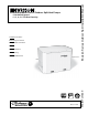
Envision Series Outdoor Split Installation Manual • R-410A Refrigerant • 2, 3, 4, 5, 6 Ton Dual Capacity Installation Information Water Piping Connections Desuperheater Connections Electrical Startup Procedures Troubleshooting Preventive Maintenance ™ IM1615 07/08 WaterFurnace Geothermal/Water Source Outdoor Split Heat Pumps
NS SPLIT INSTALLATION MANUAL Table of Contents Nomenclature 2 Physical Characteristics 2 General Installation Information 3-6 Electrical Data 7 Water Piping 8 Air Handler Nomenclature & Coil Data 9 Line Set Sizing 9 Physical Data 10 Envision Coil Nomenclature 11 Refrigerant Coil Compatability 11 Heat Recovery Unit 12-14 Wiring Schematics 15 Microprocessor Controls 16-17 Operation Logic 18 DIP Switch Settings 19 Refrigeration 20-22 Pressure/Temperature Conversion Chart 23 U
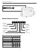
NS SPLIT INSTALLATION MANUAL Model Nomenclature 1 2 3 4-6 7 8 9 10 11 N D S 049 A 1 0 A C Model Type N = Envision Coax Options C = Copper N = Cupronickel Compressor Type D = Dual Capacity Future Option A= Cabinet Configuration S = Outdoor Split Unit Capacity Hot Water Option 0 = None Vintage A = Current Voltage 1 = 208-230/60/1 Physical Characteristics Model 026 049 064 72 Dual Capacity Scroll Compressor (1 each) Factory Charge R410a, oz [kg] 038 52 [1.47] 56 [1.
NS SPLIT INSTALLATION MANUAL General Installation Information Safety Considerations WARNING: Before performing service or maintenance operations on a system, turn off main power switches to both units. Turn off accessory heater power switch if applicable. Electrical shock could cause personal injury. Installing and servicing heating and air conditioning equipment can be hazardous due to system pressure and electrical components.
NS SPLIT INSTALLATION MANUAL General Installation Information (cont.) been made to assure that the duct system has the capacity to handle the air required for the unit application. If ducting is too small, as in replacement of heating only systems, larger ductwork should be installed. All existing ductwork should be checked for leaks and repairs made accordingly. The duct systems and diffusers should be sized to handle the design airflow quietly.
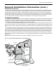
NS SPLIT INSTALLATION MANUAL General Installation Information (cont.) Connection to Air Coil Figures 1 and 2 illustrate typical Envision Split installations. The table on page 9 shows typical lineset diameters and maximum length. Linesets over 60 feet are not recommended. If the lineset is kinked or deformed and cannot be reformed, the bad section of pipe should be replaced. A restricted lineset will affect unit performance.
NS SPLIT INSTALLATION MANUAL General Installation Information (cont.) Dual Fuel Systems Envision units can be connected to fossil fuel furnaces that include an A-coil or slab coil. Dual fuel installations utilize the Envision heat pump for heating until the point that auxiliary heat is called for on the thermostat. At that point, the furnace will be enabled and the heat pump will be disabled. The Envision heat pump provides air conditioning through the furnace’s refrigerant coils.
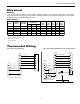
NS SPLIT INSTALLATION MANUAL Electrical General Be sure the available power is the same voltage and phase as that shown on the unit serial plate. Line and low voltage wiring must be done in accordance with local codes or the National Electric Code, whichever is applicable. See unit electrical data for fuse or cicuit breaker sizing information.
NS SPLIT INSTALLATION MANUAL Water Piping Residential NS split units are supplied standard with brass water connections which will connect to flow center. CAUTION: Never use flexible hoses smaller than 1-inch inside diameter on the unit and limit hose length to 10 feet per connection. Check carefully for water leaks. CAUTION: Water piping exposed to outside temperatures may be subject to freezing. Water Piping The proper water flow must be provided to each unit whenever the unit operates.
NS SPLIT INSTALLATION MANUAL Air Handler Nomenclature
NS SPLIT INSTALLATION MANUAL Physical Data /W` 6O\RZS` ;]RSZ
NS SPLIT INSTALLATION MANUAL Envision Coil Nomenclature <@ / 1 $ 1 1OPW\Sb 1 + 3\QOaSR C + C\QOaSR ;]RSZ Bg^S <@ + 3\dWaW]\ @ST`WUS`O\b 1]WZ <6 + 3\dWaW]\ 6gR`]\WQ 1]WZ 1O^OQWbg @ST`WUS`O\b ;]RSZa $ ;0BC6 !$ ;0BC6 "& ;0BC6 $ ;0BC6 6gR`]\WQ ;]RSZa $ ;0BC6 1]\TWUc`ObW]\ / + / 1]WZ 1]WZ <]bS( /ZZ @ST`WUS`O\b 1]WZa W\QZcRS BFD BVS S\QOaSR Q]WZ QOPW\Sb Wa RSaWU\SR T]` c^TZ]e O^^ZWQObW]\a Refrigerant Coil Compatibility Encased/Uncased Coil Indoor Split Model (Single) NRAC026* NR
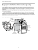
NS SPLIT INSTALLATION MANUAL Heat Recovery Unit for Domestic Hot Water Service valves have been provided inside the unit for connecting the discharge gas line to a water heating heat recovery unit (see figure 5). To make the connections, close the service valves inside the unit by turning clockwise. Using a recovery canister connect to either of the schrader ports on the DSH service valves and recover the small amount of refrigerant trapped inside of the U-tube.
NS SPLIT INSTALLATION MANUAL Heat Recovery Connections To maximize the benefits of the heat recovery a minimum 50-gallon water heater is recommended. For higher demand applications, use an 80-gallon water heater or two 50-gallon water heaters connected in a series as shown below. Electric water heaters are recommended. Make sure all local electrical and plumbing codes are followed when installing a heat recovery.
NS SPLIT INSTALLATION MANUAL Plumbing Installation 1. Inspect the dip tube in the water heater cold inlet for a check valve. If a check valve is present it must be removed or damage to the desuperheater circulator will occur. 2. Remove drain valve and fitting. 3. Thread the 3/4-inch NPT x 3-1/2-inch brass nipple into the water heater drain port. 4. Attach the center port of the 3/4-inch FPT tee to the opposite end of the brass nipple. 5.
NS SPLIT INSTALLATION MANUAL Wiring Schematics Envision Series - Dual Capacity Split Wiring Schematic - 208-230/60/1 Notes: 1 - 24V Accessory relay (see SW2 - 3 for description of operation ) S 2 – This Switch allows the unit to down stage with the t -stat when OFF and finish on second stage when ON. Finish second stage reduces stage changing in recip dual capacity compressors and should be ON for unzoned Dual Cap E -Series or Premier 2 speed units.
NS SPLIT INSTALLATION MANUAL Microprocessor Control Startup Hot Water Justification The unit will not operate until all the inputs and safety controls are checked for normal conditions. At first power-up, a four-minute delay is employed before the compressor is energized. Since compressor hot gas temperature is dependant on loop temperature in cooling mode, loop temperatures may be too low to allow proper heating of water.
NS SPLIT INSTALLATION MANUAL Microprocessor Control (cont.) high speed if in dehumidification mode). The Comfort Alert will delay the second stage compressor until 5 seconds after it receives a “Y2” from the board. Fan (G only) The fan starts on low speed (PSC ON). Regardless of fan input “G” from thermostat, the fan will remain on low speed for 30 seconds at the end of each heating, cooling or emergency heat cycle.
NS SPLIT INSTALLATION MANUAL Operation Logic Data OPERATION LOGIC STG1 HEATING STG2 STG3 EMERG COOLING STG1 STG2 FAN ON SL1 - IN ON SL2 - IN ON - - DUAL CAPACITY UNITS Compressor-Lo Compressor-Hi On Off Off On Off On Off Off On Off Off On - Rev Valve Off Off Off Off On On - - - Loop Pump On On On Off On On - On - DHW Pump On On Off Off On On - - - Secondary 1- Out On On On Off On On - - - Secondary 2- Out Off On On Off Off On - - - Emerg L
NS SPLIT INSTALLATION MANUAL DIP Switch Settings DIP SWITCH NUMBER SW1 SW2 DESCRIPTION OFF POSITION N/A NOT USED N/A N/A 1 Service/Test Mode - Allows control of “NORM” or “TEST” operational modes. Test mode accelerates most timing functions 16 times to allow faster troubleshooting. Test mode also allows viewing the “CURRENT” status of the fault inputs on the LED display.
NS SPLIT INSTALLATION MANUAL Refrigeration The Envision series comes with a holding charge. The charge must be adjusted in the field based on performance. Refrigeration piping on the split consists of installing a brazed copper line set between the blower coil unit and the unit’s split compressor section. To select the proper tube diameters for the installation, refer to the table on page 9. Line sets over 60 feet long are not recommended because of oil return and pressure drop problems.
NS SPLIT INSTALLATION MANUAL Refrigeration (continued) Leak Testing The refrigeration line set must be pressurized and checked for leaks before purging and charging the unit. To pressurize the line set, attach refrigerant gauges to the service ports and add an inert gas (nitrogen or dry carbon dioxide) until pressure reaches 60 to 90 PSIG. Never use oxygen or acetylene to pressure test. Use an electronic leak detector or a good quality bubble solution to detect leaks on all connections made in the field.
NS SPLIT INSTALLATION MANUAL Refrigeration (continued) 1. Once the proper superheat setting has been achieved, replace and tighten the seal cap. Warning: There are 8 total (360°) turns on the superheat adjustment stem from wide open to fully closed. When adjusting the superheat stem clockwise (superheat increase) and the stop is reached, any further clockwise turning adjustment will damage the valve. Determining Subcooling 1.
NS SPLIT INSTALLATION MANUAL Pressure/Temperature Coversion Chart for R-410A PRESSURE (PSIG) 60 62 64 66 68 70 72 74 76 78 80 82 84 86 88 90 92 94 96 98 100 102 104 106 108 110 112 114 116 118 120 122 124 126 128 130 132 134 136 138 140 142 144 146 148 150 152 154 156 158 160 162 164 166 168 170 172 174 176 178 TEMP °F 8.5 9.9 11.2 12.5 13.8 15.1 16.3 17.5 18.7 19.8 21.0 22.1 23.2 24.3 25.4 26.5 27.5 28.6 29.6 30.6 31.6 32.6 33.5 34.5 35.4 36.4 37.3 38.2 39.1 40.0 40.9 41.7 42.6 43.4 44.3 45.1 45.9 46.
NS SPLIT INSTALLATION MANUAL Unit Operating Parameters Dual Capacity Models First Stage Operation Cooling -- No Desuperheater Entering Water Temp °F 50 70 90 Water Flow GPM/Ton 1.5 3.0 1.5 3.0 1.5 3.
) F 7 4 3 9 2 5 2 3 8 7 8 1 7 8 5 8 9 9 2 5 0 2 7 8 4 5 8 9 NS SPLIT INSTALLATION MANUAL Pressure Drop and Recommended Flow Rates Dual Capacity 110°F 0.7 1.3 2.2 3.6 1.1 2.3 3.9 5.8 0.8 1.6 2.6 4.8 0.6 1.7 3.3 5.4 0.8 1.7 3.0 5.1 1.8 2.9 4.3 7.2 2.2 3.3 4.4 7.
NS SPLIT INSTALLATION MANUAL Unit Startup Before Powering Unit, Check The Following: • • • • • • • • • • • • • • • • High voltage is correct and matches nameplate. Fuses, breakers and wire size correct. Low voltage wiring complete. Piping completed and water system cleaned and flushed. Air is purged from closed loop system. Isolation valves are open, water control valves or loop pumps wired. Condensate line open and correctly pitched. Transformer switched to 208V if applicable.
NS SPLIT INSTALLATION MANUAL 15. Adjust the heating setpoint below room temperature and verify that the compressor and water valve or loop pumps deactivate. 16. During all testing, check for excessive vibration, noise or water leaks. Correct or repair as required. 17. Set system to desired normal operating mode and set temperature to maintain desired comfort level. 18. Instruct the owner/operator in the proper operation of the thermostat and system maintenance.
NS SPLIT INSTALLATION MANUAL Unit Startup/Troubleshooting Heating Cycle Analysis Measure suction temperature here at TXV bulb in cooling modes. Measure suction temperature here at TXV bulb in heating modes.
NS SPLIT INSTALLATION MANUAL Troubleshooting Standard Microprocessor Controls To check the unit control board for proper operation: 1. Disconnect thermostat wires at the control board. 2. Jumper the desired test input (Y1, Y2, W, O or G) to the R terminal to simulate a thermostat signal. 3. If control functions properly: • Check for thermostat and field control wiring (use the diagnostic inputs mode). 4.
NS SPLIT INSTALLATION MANUAL Preventive Maintenance Water Coil Maintenance 1. Keep all air out of the water. An open loop system should be checked to ensure that the well head is not allowing air to infiltrate the water line. Lines should always be airtight. 2. Keep the system under pressure at all times. It is recommended in open loop systems that the water control valve be placed in the discharge line to prevent loss of pressure during off cycles.
NS SPLIT INSTALLATION MANUAL Physical Dimensions Cabinet Dimensions and Refrigerant Piping Connections Top View B Front View Connection Point for Field Installed Heat Recovery Unit Rear View WATER OUT D E WATER IN J F Suction Line Connection K H G I L Lineset connections are braze type internally mounted Liquid Line Connection Side View Side View A C M PHYSICAL DIMENSIONS MODEL NS026 thru NS072 A B C D E F G H I J K L M 36.0 23.9 25.7 9.3 7.1 9.0 5.6 8.2 10.7 18.
Installation Notes:
Manufactured by WaterFurnace International, Inc. 9000 Conservation Way Fort Wayne, IN 46809 www.waterfurnace.com Product: Type: Size: Document: 7; $ # % & Envision Series - NS Outdoor Split Geothermal/Water Source Heat Pumps 2-6 Tons Installation Manual WaterFurnace Renewable Energy has a policy of continuous product research and development and reserves the right to change design and specifications without notice. ©2008 WRE.