
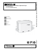
- Envision Geothermal/Water Source Outdoor Split Heat Pumps Installation Manual


8
NS SPLIT INSTALLATION MANUAL
Water Piping
Residential NS split units are supplied standard with brass water connections which will connect to ow center.
CAUTION: Never use exible hoses smaller than 1-inch inside diameter on the unit and limit
hose length to 10 feet per connection. Check carefully for water leaks.
CAUTION: Water piping exposed to outside temperatures may be subject to freezing.
Water Piping
The proper water ow must be provided to each unit whenever the unit operates. To assure proper ow, use pressure/
temperature ports to determine the ow rate. These ports should be located at the supply and return water connections on
the unit. The proper ow rate cannot be accurately set without measuring the water pressure drop through the refrigerant-to-
water heat exchanger.
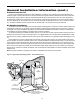
Closed Loop - Earth coupled Systems (Outdoor Installations)
Locate unit on an air pad with access hole as shown below. When mounting on an existing concrete pad, holes must
be bored through to accommodate 1 1/4-inch P.E. pipe with 1/2-inch insulation.
Connecting To Earth Loop
The earth loop trench should be continued directly under the unit as shown in Figure 3. Make the connections to op-
tional ttings from the loop circulator pump(s) and insure proper backll to support the loop pipe during trench settling. All 1
1/4-inch piping should be insulated with a minimum of 1/2-inch closed cell insulation from below the ground surface to the
loop circulator.
IMPORTANT
- A freeze protection thermostat is installed in the unit to automatically start loop
circulator pump if loop temperature drops below 20°F. Loop freeze protection should also be maintained
to the lowest temperature the insulated loop may encounter in the case of power failure.
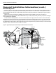
Flow Center Installation
Flow centers FC1-GL or FC2-GL, as needed, may be
internally mounted on the NDS splits, Two stub tubes with
barbs are pre connected to the coax. Two tubes with brass
ttings, to adapt to the ow center, 2 hoses to connect
between the two sets of tubes, and four hose clamps are in-
cluded with each NDS unit. The brass adapter ttings have
plastic swivel connectors and are also internally threaded to
accept 1” NPT ttings.
NOTE: For ease of installation, attach provided hoses to
coax rst and then trim to t to elbows on ow center.
Loop Supply
and Return
Piping
Figure 3: Typical Split System Outdoor Installation Using
Closed Loop